Steel-glass Composite Structures

Since its ancient beginnings as lavish window panes in Pompeii, glass has evolved into one of the most durable and versatile building materials. Today, architects and engineers are embracing the marriage of steel and glass to create striking, innovative structures that go far beyond windows – think facades, bridges, staircases, and floor slabs.

Revolutionizing Architectural Design: Steel-Glass Composite Structures

Since its ancient beginnings as lavish window panes in Pompeii, glass has evolved into one of the most durable and versatile building materials. Today, architects and engineers are embracing the marriage of steel and glass to create striking, innovative structures that go far beyond windows – think facades, bridges, staircases, and floor slabs.

The past century has witnessed a surge in steel-glass composite constructions, which have become a hallmark of modern architectural design. Over the past two decades, these hybrid structures have not only garnered significant commercial interest but have also been the subject of extensive research.

At the heart of these composite structures lies adhesive bonding, a method that fuses steel and glass elements to form constructions with exceptional load-bearing capacity, stability, ductility, and toughness. This unique combination of properties has revolutionized the way buildings are designed and constructed.

Selecting the Right Materials for Steel-Glass Composites

To create an effective steel-glass composite structure, careful consideration must be given to the mechanical properties of the materials involved, such as strength and stiffness. Adhesives, in particular, require thorough testing to ensure they meet the performance requirements of the overall structure.

Standardized tests should be conducted on both bulk and shear specimens for adhesives, as well as connection tests on smaller specimens. Since technical descriptions of adhesives often lack sufficient information, it is crucial to determine characteristic values and safety factors, if possible.

As architects and engineers continue to push the boundaries of design, steel-glass composite structures will undoubtedly play a pivotal role in shaping the future of the built environment. These innovative constructions not only offer unparalleled aesthetic appeal but also provide a highly efficient and sustainable alternative to traditional building materials. By carefully selecting the right materials and rigorously testing adhesive bonds, we can create awe-inspiring, resilient, and lasting architectural masterpieces that will stand the test of time.

Steel Selection

When designing steel-glass composite structures, it's generally assumed that the steel component's yield stress will not be reached before the glass fails. As a result, steel grade A283C is often sufficient for most applications when paired with the appropriate adhesives. However, for projects requiring exceptionally strong epoxy resins, the use of A570Gr40 or higher is recommended, depending on steel and glass cross-sections and pre-design stress calculations.

To ensure excellent adhesion and prevent failure, proper surface treatment of the steel is essential. Utilizing certified technologies for surface pre-treatment, preparation, and activation, preferably from adhesive producers, helps guarantee optimal bonding performance.

Glass Selection

The maximum load a steel-glass structure can handle is directly related to the type of glass used. The overall resistance of such hybrid structures depends on the permissible stresses of the materials. When selecting the glass component for your project, it is crucial to adhere to the various governing code processes. These processes involve:

  • Determining the mechanical specifications.

  • Defining the material's qualities.

  • Detailing the various behaviors and their combinations.

  • Assessing the product's permissible capacity.

  • Identifying the type and dimensions of the glass.

By carefully selecting the right steel and glass materials and adhering to widely-accepted design processes, architects and engineers can create steel-glass composite structures that not only meet American standards but also push the boundaries of design and functionality.

Steel-glass Beams And Columns

Hybrid steel-glass beams and columns are composite structural elements made of glass webs and steel flanges that are adherent-bonded together. Combining these components in any building component enables the structural engineer to take advantage of the steel’s strength and ductility while giving the architect access to the glass’s aesthetic appeal. The combination of glass and steel gives the building a light and airy aspect while minimizing its obtrusiveness and maximizing the amount of natural light it can receive. Building occupants’ productivity and health are proven to improve with natural daylight, and it also lowers the need for electric lighting, which lowers carbon emissions. Glass and steel provide the sense of a contemporary, spotless setting where people are content to work and live.

Advantages of Steel-glass Composite Structures

There are several advantages of Steel-glass composite structures. Some of them are:

  • Aesthetics

  • Indoor Lighting

  • Durability

Aesthetics

The structural design is diversified by combining steel and glass. The irregular shapes of glass-steel buildings allow designers to convey their design thoughts in more artistic ways than standard steel structures with straight members, which raises the aesthetic value of the planned structure. Glass panels can have their qualities exactly tailored by utilizing various surface coloring, printing, and processing techniques. Architects may create vibrant urban landscapes using a number of design concepts thanks to the variety of glass textures.

Indoor Lighting

Steel-glass structures are also employed to enhance indoor lighting due to the high transmittance and transparency of glass. To optimize the display setting and enhance inside illumination, steel-glass constructions are frequently employed in the fronts and interior of some commercial buildings, such as fashion boutiques. Railings made out of glass and steel are frequently utilized in public transportation terminals.

Durability

Glass materials now have a high level of resilience to buckling and breaking as a result of advancements in manufacturing methods. For instance, a laminated glass panel will have a strong resistance to buckling under an axial stress because all of the glass layers are supported by one another. If a break occurs, the glass panel’s fragmented fragments will remain connected to one another and show significant residual tension.

Potential Applications of Steel-glass Composite Structures

Innovative steel-glass structural solutions currently have promising market possibilities in the building sector. Curved glass roofs made of steel frames and glass panels have been utilized in airports and train stations. Curved glass roofs are used because they enhance both indoor lighting and temperature control.

The roofs of museums and observation decks also use the same kinds of composite structures. Glass panels and steel beams can be welded together to create glass-metal composites in advanced applications of glass-steel constructions, which have great load capacity under axial load.

Glass panels and steel supports are combined to create steel-supported glass façades in contemporary architecture. Concrete walls can be replaced with steel-supported glass façades for some temporary projects.

When building skyscrapers, high-strength glass panels and steel frames can be used to create high-performance curtain walls that serve as the exterior façade of tall structures.

Design Considerations and Costing For Steel-glass Composite Structures

Steel-glass buildings are primarily intended to increase the indoor illumination, openness, and elegance of public facilities. Due to this design purpose, a structural form with several glass panels and arched supporting frames is constructed. Curved steel-glass roofs are less expensive than conventional roof types. By streamlining structural detailing, lowering the cost of flashing, and eliminating vertex stitching for spans under 80ft, the increased expense brought on by the curved steel frame can be offset.

Most glass panels can fit straight into the curved roof during installation, therefore pre-bending is typically not necessary for roof cladding on curved roof beams. Although attaching several straight members can potentially provide the planned spindle torus’ curved form, doing so would result in a large rise in production costs. Contrarily, a structural design that makes use of curved frames will be more economical.

The boundary conditions of the glass panel should be established prior to developing the curved frame for a glass-steel construction. After that, a sturdy curving roof should be created based on how rigid the glass panel membrane is. Avoiding excessive bending of any glass panels is required to maintain the stability of curved glass panels above the frame. Therefore, the proper geometry for each glass panel should be established during the design stage to enable the membrane to act only on its own weight.

Architectural Considerations

The architect should adhere to a few fundamental guidelines about the proportions and arrangement of the glass-steel elements in order to maximize the architectural potential of glass-steel constructions.

To prevent seams along the length of the beam, the webs of glass-steel beams should, whenever possible, be constructed from a single piece of glass. This places a 20ft length restriction on glass-steel beams. In order to maximize the area ratio of glass to steel in terms of aesthetics and structural strength, the aspect ratio of the beam should be selected. In general, the beam will be more transparent the larger the glass web area in relation to the steel flange. However, when structural concerns are taken into account, there are obviously constraints.

The Installation height and the separation between the beams both affect transparency. Hybrid beams should typically be installed between 10 and 20ft high; tests have shown that if the height is more than 20ft, the steel flanges conceal the glass web from view from the ground.

The design of steel-supported glass façade systems is governed by similar principles. The largest glass pane size that can be used in this situation is an important factor. Joints are a given in façades, save for the tiniest constructions. However, by lining up the joints with the sustaining wind posts, their influence can be reduced. The Inclusion of circular or oval tubular sections can enhance the look of the wind posts.

Structural Considerations

The structural engineer, as in any structural design situation, must strike a balance between the requirements of the application and the capabilities of the materials. Understanding the advantages and disadvantages of each individual component, as well as the best approach to combine them, is essential to achieving this balance in any composite or hybrid solution.

As opposed to the steel, which has strong structural capabilities, glass is primarily used in the system for its aesthetic appeal. In particular, it is a brittle material with limited structural capabilities that tends to shatter under concentrated loading and evaporates at high temperatures.

Therefore, hybrid glass-steel beams must be created in a way that evenly distributes the loading and has enough flexibility to prevent overstressing the glass. The use of adhesively bonded connections, particularly with a flexible adhesive, satisfies both of these requirements. In order to prevent concentrated forces in the glass, great care must be given when describing the connections.

Glass-steel beams cannot be used in circumstances where fire resistance is necessary because of their poor performance at high temperatures. In contrast, the steel has strong structural qualities and may be used in relatively thin portions to give the hybrid beam or façade a significant amount of structural capacity. However, using too much steel may lessen the hybrid structure’s aesthetic characteristics and transparency.

Adhesives

For the design of hybrid steel-glass structures, the adhesive choice is of utmost importance. The thickness of the adhesive layer, which results from the permitted tolerances of the steel and glass components, is crucial for the mechanical behavior.

For Steel-glass structures, there are four primary adhesive innovations that can be used: Polyurethanes, Acrylates, Silicones and Epoxy resin. There is already a vast array of potential adhesives for these categories, each with a unique curing mechanism, mechanical behavior, ageing resistance, application behavior, etc. Therefore, it is advised to limit your options to cold-hardening, two-component, or UV curing systems with sufficient pot life, proper application behavior, and appropriate mechanical parameters.

Got an engineering project you need professionals for? Let's get the job done for you! You can speak with our professionals at JPC Design Consortium to get you started on your project today. Contact us right away.

Read More
STRUCTURAL ENGINEERING Daniel M. STRUCTURAL ENGINEERING Daniel M.

Timber Connection Systems

Joints and connections are essential components in timber structures, responsible for maintaining the structural integrity, stability, and performance of the assembly.

Timber is an important material for building, can be used for many different structural forms, including beams, columns, trusses, and girders. It can also be used for piles, deck members, railway sleepers, and concrete formwork. However, for timber to be used coherently to form a structure, there must be a way of joining timber components to form a structurally stable unit, and this is what we’re about to discuss.

Joints and connections are essential components in timber structures, responsible for maintaining the structural integrity, stability, and performance of the assembly. These connections can be achieved through various methods, such as traditional carpentry techniques, including mortise and tenon, dovetail, and scarf joints, or by employing modern engineered connectors, like metal plates, brackets, and screws. The choice of joint or connection depends on factors like load-bearing capacity, ease of assembly, aesthetics, and the specific requirements of the project. Proper design and execution of these connections are crucial, as they ensure the efficient transfer of forces within the structure, preventing failures or deformations. Additionally, well-designed joints and connections can accommodate the inherent properties of timber, such as moisture-induced movement and natural variability, contributing to the long-term durability and performance of timber structures.

Fasteners Used in Timber Connection Systems

Timber connections play a critical role in joining structural elements in wood-based constructions, and fasteners are key components utilized in these connections.

A fastener is a hardware device used to mechanically join or affix two or more objects together, creating a non-permanent joint that can be disassembled or adjusted without damaging the connected components. Fasteners come in various types, sizes, and materials, with specific designs tailored for different applications and load-bearing capacities.

There are several fasteners used in timber connection systems. They are;

  • Nails

  • Screws

  • Dowels

  • Bolts

  • Glue

Nails

The most used fastener in wood construction is the nail, which comes in a variety of lengths, cross-sectional areas, and surface treatments. The most popular kind of nail is a smooth steel wire nail with a circular cross-section that is made from wire coils with a minimum tensile strength of 87,000psi. It is offered in a typical range of sizes up to a maximum of 5/16 inch and can be either plain or corrosion-resistant, such as by galvanizing.

Nails can be driven manually or with portable pneumatic devices. There is a risk of excessive splitting happening when nails are pushed into dense timbers. To prevent splitting, the pointed end of the nail can be blunted so that it slices through the fibers of the wood rather than separating them, or a pre-drilled hole that is less than 80% of the nail diameter can be drilled into the wood to. Timbers having a lower characteristic density of 32lbs/ft3 are often not pre-drilled.

Screws

In addition to being useful for timber-to-timber joints, wood screws are also well suited for steel-to-timber and panel-to-timber joints. Typically, these screwed joints are created as single shear joints. In order to enter screws, they must be turned, which can be done either by hand or with a power tool, depending on the circumstance. A major advantage that a screw has over a nail is it’s withdrawal capacity.

Dowels

Dowels are circular rods with a minimum diameter of a quarter of an inch, and are made of wood, steel, or carbon-reinforced polymers. Dowels are inserted into pre drilled holes on the wooden members. In timber construction, joints made using dowels are utilized to transmit strong forces. Dowels joints are affordable and simple to create.

Bolts

Bolts are nut- and head-equipped dowel-type fasteners. Typical bolts consist of common machine bolts (M12-M14 with a coarse head) with washers that have a side length of around 3d and a thickness of 0.3d, where d is the diameter of the bolt.

Bolts will be applied through pre-drilled holes that are 1/25 inch to 1/16 inch larger, and the bolt and washer will be tightened as needed to ensure that the connection’s parts fit snugly together. When the timber reaches an equilibrium moisture content, bolts may need to be retightened if necessary.

There are four major types of bolts namely;

  • Carriage bolt

  • Hexagonal head bolt

  • Square head bolt

  • Lag screw

Glue

A glued joint is a rigid type of joint that is formed using an adhesive. Compared to mechanically secured connections, structural glued joints are typically more rigid, require less wood, and look nicer.

Timber Connectors

Timber connectors are load-transferring devices that hold the joint assembly together with bolts or lag screws. They increase the area of wood across which a weight is distributed, making them more structurally effective than bolts or lag screws when used alone. They are typically not protectively coated and only need to be galvanized if used with preservation-treated wood or in wet service conditions. They are primarily used to transfer loads in heavy timber or glulam members, such as in roof trusses. The bolt's placement and specification are crucial because they bind the joint together, enabling the connector to function properly.

There are three types of timber connectors in use. They are

  • Split Ring

  • Shear Plate

  • Toothed Plate

Split Ring

This is used for only timber to timber connections and is installed in pre-cut grooves.

Shear Plate

This type of timber connector is used for both timber to timber and timber to steel connections. It is installed in pre-cut grooves

Toothed Plate

This type of timber connector is used for both timber to timber and timber to steel connections. It is pressed into the timber.

Types of Timber Connection Systems

  • Mechanical Connections

  • Joinery

In wood structures, joinery and mechanical connections are the two main categories of connections. Many variations fall under each of these categories, offering a vast variety of choices to fit almost any architectural design.

Mechanical Connections

There are three main forms of mechanical connections used in wood structures: dowel, metal connector plates with integrated teeth, and shear. There are also a lot of proprietary connections that mix features from all of these different types.

Dowel

Most typical mechanical connections use dowel-type fasteners to join wood parts together because they effectively transfer loads and are reasonably quick and easy to install. They come in a variety of shapes, and the National Design Standard (NDS) for Wood Building can be used to calculate their strength properties. When loads are relatively light, as in multi-family and small commercial structures, nails are typically used. While the NDS does not publish design values for staples, similar capacities must be found when using staples in place of nails. Under certain circumstances (such as exposure to moisture), screws may be more effective than nails because they tend to work less loose and typically have strong wind pullout resistance. High-strength timber rivets are a type of dowel fastener that are used with specially made metal plates.

Using a combination of dowel bearing and bending of the dowel fastener, dowelled connections transfer force between members. For flooring, a glued-nailed technique is recommended. With this technique, sheathing is glued to the substrate element, whether it be wood or an I-joist, to reduce squeaks and increase stiffness because of the action of the T-beam. The last nail must be driven in before the glue hardens. Due to the lower ductility, glueing is not advised for bonding wall or roof sheathing to framing. Adhesives are not permitted in Seismic Design Category D, E, or F, although being permitted in Seismic Design Categories A, B, and C with a decreased R=1.5.

Metal Connector Plate With Integrated Teeth

Metal connection plates are used mostly with manufactured light-weight wood trusses and partially pierce the wood members because they have many rows of teeth built right into them. These connectors allow loads to be transported close to the wood member’s surface.

Shear Connectors

Shear connectors, also known as bearing connectors, are frequently employed to support greater loads. They consist of shear plates, split rings, and toothed shear plates. They are often built of cast iron or light metals and are capable of carrying loads entirely due to the bearing and shear resistance of wood in directions parallel to the grain or perpendicular to it. They may be hidden or clearly visible, and they can be used to join wood to steel members or wood to wood members.

Split rings that have been profiled using specialized machining tools are often installed in a radial groove on the meeting side of the timber components. The split in the steel rings ensures that the wood members and split ring remain in contact by allowing the gap in the ring to shut or open if the wood members shrink or swell. The joint assembly is held together by a bolt that is inserted through the middle. Shear plates require grooves to be precisely cut with specialized tools, recessing the wood so the shear plates fit flush with the surface. In structures located in high seismic regions, shear plates and split ring connections should be avoided unless the designer uses elastic seismic design.

Proprietary Connections

Some of the most cutting-edge connection systems are proprietary, meaning that they are created solely for a certain structure. The usage of connecting systems and products created for use in larger, more intricate buildings and designed to take advantage of the advantages of wood from an economic, aesthetic, and environmental standpoint has experienced significant expansion in recent years.

For instance, two framing components can be connected in a single piece using custom-fabricated structural frame connectors. They are typically made of bent or welded steel and transfer load directly from the supported part into the supporting member (by hanger flange bearing, fastener shear or a combination of the two).

The self-tapping or self-drilling screw is one example of a proprietary product that is increasingly in use, particularly in cross laminated timber (CLT) and glulam buildings. They are made by numerous companies in North America, Europe, and Japan, and come in a variety of sizes, forms, and features. They come in a variety of capacities for varied purposes and have increased hardness for stronger lateral load capacity. The key benefit is that they can be drilled into wood with a standard handheld power drill without the need for pilot holes. This reduces the possibility of errors occurring in the field and boosts efficiency and dependability.

Some of the various proprietary connections include;

  • Castings

Castings, which are often constructed of ductile steel, are used as wood connections in buildings. They offer an economical, versatile and elegant way to achieve beautiful architectural connections.

  • Tight-fit Bolt And Pins

Tight-fit bolts are just standard bolts that are inserted in bolt holes that are drilled considerably more precisely in joining steel plates and timber. According to the Eurocode, tight-fitting bolts must have a bolt hole that is either the same diameter as the bolt or up to 0.5 mm smaller. The bolt diameter must not be more than 1.0 mm bigger than the bolt hole in the steel. The same specifications apply to tight-fit pins, which typically come in the form of headless stainless steel shafts with slightly chamfered ends and are frequently used for high-end exposed connections.

  • Ring Nails

Timber rivets are replaced by ring nails in Europe. They have a circular head and are shiny, giving them a neater appearance than timber rivets. Based on empirical data, the Swiss code offers detailed recommendations for developing ductile connections. The Gunnebo nail from Sweden is one type of exclusive ring nail attachment system.

  • Self-tapping Screws

Self-tapping screws are specialized, self-drilling screws that range in size from 3/16 to 12 inch (5 mm to 12 mm) in diameter and 3 to 23 inches (8 cm to 60 cm) in length. They are made of high strength (roughly 115ksi or 800 MPa) steel.

Self-tapping screws come in three different main categories. In wood-to-wood connections, heavy tension loads are transferred without the use of a washer plate using fully threaded screws. Steel bearing plates are fastened with partially threaded screws, which also have the ability to distribute shear. They can clamp things very tightly. In order to align the panels and transfer longitudinal shear, variable pitch screws are frequently utilized in edge-to-edge connections between solid wood panels.

  • HBV And HSK System

HBV is a connector used to create composite wood-concrete floor systems. It comprises of an expanded steel mesh that is cast into the concrete above and cemented into a saw cut on top of the timber beam or solid wood panel using a specialized adhesive, rigidly joining the two together.

The HSK technique Is similar, except it’s used to join steel pieces to wood or to join two separate wood elements. It comprises of a 3/32 inch perforated steel plate that is cemented into a kerf in the timber element and welded to a steel portion in the case of a steel-to-wood connection, rigidly joining the two members.

Joinery

For traditional joinery connections (sometimes referred to as carpentry connections), such as mortice/tenon and scarf joints, connected elements are generally given notches, holes, and tongues to help them interlock. In these kinds of connections, forces are transferred in compression and bearing. Wooden, metal, or keys are needed to secure interlocked connections in stress and prevent separation.

While very popular in single-story residences, businesses, and recreational facilities, joinery connections are rarely used for contemporary, multi-story heavy timber structures. One explanation is that these connecting systems require highly developed skills that are typically only found in seasoned carpenters. These connections are labor-intensive as well, making industrial manufacturing uneconomical.

Got an engineering project you need professionals for? Let's help you get started on it! You can speak with our professionals at JPC Design Consortium to get you started on your project today. Contact us right away. 

Read More
STRUCTURAL ENGINEERING Daniel M. STRUCTURAL ENGINEERING Daniel M.

Structural Insulated Panels(SIPs)

Structural Insulated Panels (SIPs) are lightweight modular panels that are manufactured off-site and consist of insulating foam sandwiched between two panel boards, often oriented strand board (OSB). Each panel contains several layers that work together to effectively resist heat transfer. SIPs offer superior strength, durability, and energy efficiency compared to conventional insulation techniques.

SIPs consist of an insulating core or layer placed between two structural facings. Typically, this insulating core might be made of expanded polystyrene or closed-cell polyurethane foam (EPS). Due to their compliance with the the various British, European and American codes for structural integrity, Oriented Strand Boards (OSB) are most often used for structural facings. In addition to OSBs, other materials utilized as structural components include cement, metals, engineered wood, magnesium oxide board, and cement.

Manufacturers typically have the ability to alter the exterior and interior sheathing materials to meet specific customer needs. The foam core and facing are joined with an adhesive. The sheathing and core are then joined together by applying pressure to the panel or by placing it in a vacuum. An insulated foam core sandwiched between two rigid board sheathing layers makes up structural insulated panels.

Expanded polystyrene (EPS), extruded polystyrene (XPS), and polyurethane foam are typically the foam core materials (PUR). The assembly is pressure laminated together using EPS and XPS foam. The liquid foam is injected and cured under high pressure with PUR and PIR. Oriented strand boards are the most typical sheathing boards (OSB). Sheet metal, plywood, fiber-cement siding, magnesium-oxide board, fiberglass mat, and gypsum are some further sheathing materials.

SIPs are produced in a range of sizes and thicknesses, from 4 to 8 inches. As soon as they are delivered on site, they may be swiftly fitted because they are usually properly cut and sized from the factory. SIPs can be produced and customized based on the project’s needs.

Features of Structural Insulated Panels

SIPs, or structural insulated panels, are high-performance insulating panels that are used to construct the walls, ceilings, and floors of residences and small enterprises. Some of its key features are:

  • Structural strength

  • Thermal barrier

  • Lightweight

  • Moisture resistance

  • Adaptability

  • Quick build times

  • Acoustics

Structural Strength

SIPs can withstand heavy vertical and horizontal stresses by passing the loads to the ground through the OSB skins, which are held together by the insulated core. SIPs are a great option for walls, floors, and roofs because of their structural strength. They can be used as infill walls or load-bearing structural walls, depending on the situation. SIPs are capable of supporting loads in structures up to four stories.

Thermal Barrier

The main component of SIPs is insulating foam, which offers natural thermal insulation embedded into the structure and helps to reduce U-values. Since SIPs are panelized, they are highly airtight, which helps maintain a thermal barrier between the inside and the outside by limiting the transmission of air through the walls, floor, and roof.

Lightweight

In comparison to its structural strength, SIPs’ OSB skins and insulating foam composition offer a lightweight solution. Structural insulated panels are significantly lighter than some others on the market because to the ployurethane (PUR) insulating foam that is injected between the OSB skins.

Moisture Resistance

SIP panels are designed with moisture resistance in mind to ensure durability and prevent issues such as mold growth and structural degradation. The closed-cell structure of the insulation materials, like EPS and PUR foam, helps resist moisture absorption, reducing the potential for water infiltration and damage. Additionally, the airtight construction of SIPs minimizes the flow of moist air through the building envelope, thus mitigating the risk of condensation within the walls. Proper installation and sealing techniques, coupled with appropriate moisture management strategies, such as utilizing vapor barriers and maintaining adequate ventilation, further contribute to the moisture resistance of SIP buildings. This combination of design features and construction practices ensures a healthier, more durable, and energy-efficient building environment.

Adaptability

SIPs’ modular design enables a variety of combinations that can be utilized for roofs, floors, internal, exterior, and party walls. This makes it possible to employ SIPs for entire buildings or only a portion of them.

Faster Construction

SIPs’ panelized construction makes it possible to erect structures fast and with little on-site labor. There is less need for stud wall framing and insulation materials on the internal walls because the panels combine structural features with embedded insulation, which further reduces the entire building time.

Acoustic Ability

Structural Insulated Panels (SIPs) offer impressive acoustic performance, providing a comfortable and quiet living environment in residential and commercial settings. The high-quality insulation materials used in SIPs, typically expanded polystyrene (EPS) or polyurethane (PUR) foam, effectively reduce sound transmission between spaces. This superior sound attenuation is further enhanced by the airtight construction and the absence of thermal bridging, which minimizes the paths for sound to travel through. As a result, SIP buildings typically have lower levels of noise infiltration, making them ideal for applications where noise reduction is a priority, such as urban housing, offices, and schools.

Types of Structural Insulated Panels (SIP’s)

There are primarily three types of SIPs, depending on the insulating material used in producing them:

  • Expanded polystyrene insulated panels

  • Polyurethane insulated panels

  • Compressed straw-core insulated panels

Expanded Polystyrene Insulated Panels

Expanded polystyrene (EPS) panels act as the insulation panel in composite sandwich panels with EPS insulation as the core. In the construction industry, EPS panels have a wide range of applications. They are useful for insulation of cavity walls, ducts, and floors as well as packaging, void filling, floor raising, and other tasks. High density panels are suggested for uses like floor lifting and insulation. In packaging applications, panels with low density and high resistance can be used.

Polystyrene beads are used to create EPS panels, and they are heated during a chemical procedure to cause the beads to expand to their final size. Once they have combined, they are squeezed through various moulds into EPS blocks of various sizes while being sandwiched between PPGI sheets. They are further chopped and formed to meet the needs of various industries. Moreover, they are adaptable and can be produced in various densities in accordance with customer needs. Due to their extreme toughness and longevity, EPS panels are a good choice and work best for both walls and roofing.

The R-value of these SIPs ranges from R-4 to R-5 for each inch of thickness. This number may increase to 13.8. There are EPS panels on the market with widths ranging from 4 to 24 feet.

Polyurethane Insulated Panels

Polyurethane Insulation Panels are adaptable and can be used for interior or exterior walls, partitions, roofing, and ceiling in commercial, industrial, or residential structures, warehouses, cold rooms, clean rooms, factory buildings, prefab containers, and cabins. Particularly effective in sectors like food processing, refrigeration, pharmaceuticals and drug storage, fish and dairy, etc. are polyurethane panels. You can create cold and normal temperature zones within your interior space using insulated barriers.

Insulated panels made of polyurethane or polyisocyanurate have a nominal R-value of R-6 to R-7 per inch of thickness. The thickness of these insulated panels is 3.5 inches for walls and 7.5 inches for ceilings. Compared to EPS, polyurethane panels are more expensive, but they also provide better water and fire protection and a higher R-value.

Compressed Straw-core Insulated Panels

In contrast to other panel materials, these are made from recycled and regenerated waste agricultural straw. They offer superior thermal insulation, thermal storage, sound insulation, and a high resistance to mold, pests, and fire. They are also environmentally friendly.

Unlike conventional panel materials, compressed straw-core insulated panels are “green construction materials” made from recycled and renewable waste agricultural straw. While being environmentally beneficial, they offer a narrower range of R-values than other varieties of SIPs.

Advantages of Structural Insulated Panels

A well-constructed home made of SIPs will have a tighter building envelope and walls with greater insulation values, which reduces drafts and lowers running costs. Additionally, because SIPs are standardized and all-in-one, they can be built in less time and with fewer workers than a frame house. The panels can be used as a floor, wall, or roof. Its benefits include;

  • Enhanced insulation

  • Durability

  • Energy saving

  • Sustainable building

  • Faster construction

  • Flexible Design

Enhanced Insulation

In SIPs, two surfaces are sandwiched with a layer of rigid foam insulation. As a result, they are far more energy-efficient than conventional building materials. They are more effective in controlling temperature, keeping interiors warm in the winter and keeping them cool in the summer. Residents can live in significantly quieter homes thanks to the insulation’s contribution to the reduction of noise penetration.

Durability

SIPs are substantially stronger than comparable surfaces produced from conventional frames. They are lighter and easier to transport and can span up to 18 feet through floors and roofs without adding support. Extreme weather conditions can also be withstood by buildings made of SIPs panels.

Energy Savings

The energy efficiency of SIPs is said to be roughly 50% higher than that of conventional timber framing. Houses are more airtight and don’t lose as much heat, which lowers homeowners’ energy costs and the amount of carbon emitted into the atmosphere. Furthermore, the decreased air movement enables better air quality and controlled indoor temperature.

Sustainable Building

SIP construction uses a lot less energy than conventional construction techniques while creating a structure. Since panels are made in facilities offsite and transported to their final location, there is less garbage disposed of in landfills and less noise pollution for nearby businesses and households.

Faster Construction

Construction may proceed swiftly once the panels are placed because all SIPs walls, roofs, and floors can be precisely designed and manufactured offsite. For instance, a flooring installation that often takes a few days can be finished in a matter of hours.

Flexible Design

Compared to traditional construction methods, SIPs give architects more flexibility and creative freedom to design aesthetically beautiful structures. For the best contemporary designs, the panels can also be used with various building materials like brick, stones, wood, tiles, and glass.

Applications of Structural Insulated Panels

Structural insulated panels(SIP’s) are appropriate for a variety of applications due to their many advantages. Some of them include;

  • SIPs are employed in commercial buildings where the presence of machinery and equipment may result in greater temperatures. Under these circumstances, these panels effectively manage the temperature inside.

  • SIPs, particularly in pharmacies, offer the required temperature for the storage of medications and medical supplies. These panels are used in refrigerated trucks to deliver medications and other temperature-sensitive medical supplies.

  • SIPs are used for industrial-scale cooling to coat the walk-in freezers and refrigerators to maintain the proper temperature. These facilities are used by hospitals, schools, restaurants, campers, etc.

  • In order to keep the interior of warehouses cold, SIPs are utilized. It is appropriate for warehouses where food, electronics, and other temperature-sensitive goods are kept.

Got an engineering project you need professionals for? Let's get the job done for you! You can speak with our professionals at JPC Design Consortium to get you started on your project today. Contact us right away.

Read More
STRUCTURAL ENGINEERING Daniel M. STRUCTURAL ENGINEERING Daniel M.

Retaining Walls And Gabion Walls

Retaining walls are rigid structures designed to support soil laterally so that it can be held at various heights on the two sides. The purpose of retaining walls is to hold soil to a slope that it would not naturally follow (typically a steep, near-vertical, or vertical slope). They are frequently utilized in terrain with unfavorable slopes or in regions where the environment needs to be drastically changed and constructed for more specialized purposes, including hillside farming or traffic overpasses. A seawall or bulkhead is a retaining wall that retains soil on the backside and water on the front.

A retaining wall is designed to hold certain items in place, such as the edge of an excavation or a terrace. The structure is made to withstand the lateral pressure of soil when the required change in ground elevation exceeds the angle of repose of the soil.

The most important component of effective retaining wall design and construction is recognizing and thwarting the tendency of the trapped material to move downslope due to gravity. As a result, there is lateral earth pressure behind the wall. The magnitude and direction of this movement, as well as the angle of internal friction (phi) and cohesive strength of the held material, all affect how much movement the retaining structure experiences.

At the top of the wall, lateral earth pressures are zero, and in uniform ground, they rise proportionately to a maximum value at the lowest depth. If the problem is not solved, earth pressures will force the wall forward or cause it to collapse. Moreover, hydrostatic pressure on the wall is caused by any groundwater behind the wall that is not eliminated by a drainage system. For lengthwise sections of uniform height, the whole pressure or thrust may be assumed to act at a third from the lowest depth.

To keep the pressure within the wall's design value, effective drainage is essential behind the wall. The hydrostatic pressure will be reduced or eliminated by drainage materials, which will also increase the stability of the material behind the wall.

 Types of Retaining Walls

Retaining walls can be classified into several categories based on their structure, materials, and construction methods. Here are some common classifications of retaining walls:

By Structure:

Gravity retaining walls
Reinforced retaining walls
  • Cantilever retaining walls

  • Counterfort retaining walls

  • Precast retaining walls

  • Pre-stressed retaining walls

 Classification by materials
  • Concrete retaining walls

  • Masonry retaining walls

  • Stone retaining walls

Reinforced soil walls

  • Reinforced soil

  • Soil nailing

Hybrid System

  • Anchored earth retaining walls

  • Tailed gabion walls

Sheet pile walls

Gravity Walls

Gravity walls use their enormous weight to hold the material behind them and establish stability against breakdowns. A gravity-retaining wall can be built out of brick, stone, or even concrete. Gravity-retentive walls are much thicker in section. These walls’ geometry aids in their stability as well. Walls made of mass concrete are appropriate for retained heights up to 3 m. The wall’s stability, how it uses the area in front of it, the required wall appearance, and the construction technique all have an impact on the cross-sectional shape of the wall.

Reinforced Retaining Walls

On spreading foundations, reinforced concrete and reinforced masonry walls are gravity structures whose stability against overturning is given by the weight of the wall and its reinforcement bars. The most common wall types are as follows:

Cantilever Walls

A wall that is attached to the foundation is a cantilever retaining wall. A cantilever wall must be carefully designed because it holds back a lot of soil. They are the kind of retaining wall that is most frequently used. Cantilever walls are supported by a block of ground. The weight of the backfill and surcharge, which is also loaded onto this slab base, stabilizes the wall against toppling and sliding.

Counterfort Walls

Counterfort walls are cantilever walls that are reinforced with monolithic counterforts made of the base and rear slabs of the wall. The counter-forts link the wall slab and the base and serve as tension stiffeners to lessen bending and shearing stresses. Counterforts are employed to decrease the bending moments in tall vertical walls, with their spacing being equal to or slightly greater than half the height. For high walls over 8 to 12 meters high, counter forts are used.

Precast Retaining Walls

Precast retaining walls are concrete structures vibrated to retain soil. They are made up of a row of full-height modular plates. On the side that is exposed to the soil, there may be one or more vertical strengthening ribs that run from the base of the wall to its peak. They can be positioned atop a prefabricated foundation of different sizes that has already been built. The two parts are then held together using a concrete pour.

Prestressed Retaining Walls 

For the purpose of constructing a continuous, consistent concrete retaining wall, prestressed concrete panels are often laid between steel columns. Because of its distinctive design, pre-stressed concrete is intrinsically stronger than conventional concrete. Before installation, panels are crushed and tensioned using steel tendons, making the concrete panels more resilient to tension. Also, this lessens the chance of the concrete cracking.

Masonry Retaining Walls

A masonry retaining wall is a construction made of materials like stone that is intended to keep dirt, rock, and other materials in place. The term “masonry” refers to a construction method in which material blocks are piled and cemented together. Stone, brick, glass, ceramic, concrete blocks, and other materials are examples of these materials. A well-constructed stone retaining wall has the potential to be both extremely durable and visually appealing.

Reinforced Soil Walls

This category comprises reinforced soil and soil nailing and includes walls that use soil that has been reinforced with reinforcing bars to form a sturdy earth retaining system. Reinforced soils can be used to construct retaining walls in the following ways:

  • As an essential component of the design.

  • As an alternative to the use of reinforced concrete.

  • To serve as temporary works.

  • As repairs or upgrades to an existing configuration.

Soil Nailing 

When building a soil-nailed wall, the earth is reinforced as excavation continues by the addition of passive bars, or bars that essentially work in tension. Typically, they run parallel to one another and are slanted downward. These bars can also function partially under shear and bending.

Hybrid System

Hybrid or Composite retaining wall systems are the kind of retaining walls that rely on both their mass and reinforcements for stability. They include the following:

Anchored Earth Retaining Walls 

An anchored earth wall is any structure that uses facing components fastened to rods or strips with the ends anchored into the ground. Similar to abutments are the anchors. Often, high strength, pre-stressed steel tendons are employed as the tying cables. The ends of the strips are shaped to bond the strip at the point into the soil in order to enhance anchorage.

Tailed Gabion Walls

In civil engineering, road construction, military applications, and many other fields, gabions are cages, cylinders, or boxes filled with soil or sand. Rip-rap with cages is used to control erosion, while metal constructions are employed for creating foundations or dams.

Sheet Pile Walls

Steel sheets are driven into an excavation or slope until they reach the desired depth to create steel sheet pile walls. Their most frequent application is in short-term, deep excavations. They are thought to be most cost-effective in situations when soft soil retention at greater earth pressures is required. It is unable to withstand extreme pressure.

Functions of Retaining Walls

Retaining walls provide a variety of advantages that can help turn your environment into a beautiful and useful work of art. They are;

Structural Support

The purpose of a retaining wall is to hold soil in place. This mainly applies to terrain with minor slopes, where these walls serve as a required barrier to stop soil from moving forward during a landslide. Due to this, a retaining wall is a requirement for your landscape’s safety, assuring both your safety and the safety of your home.

Preventing Erosion And Improving Drainage

All landscape will eventually experience erosion, whether it be brought on by wind or water. Because of this, retaining walls are even more crucial, particularly if your landscape lacks a lot of trees and bushes to keep the soil in place. Retaining walls aid in minimizing sharper gradients, which not only maintain the soil but also aid in lowering surface runoff. This slows down the rate at which water flows over the surface, which lessens erosion.

Retaining walls accomplish all of this while also offering efficient flood control through water drainage designed to reduce floods. To add additional safeguards for appropriate drainage and water control, channels and drainage pipes can be incorporated into the construction. Finally, by terracing the area around the retaining wall, which allows water to percolate into the soil rather than run off the surface, the gradient is also reduced.

Aesthetics

Depending on their height and the type of material they are made of, retaining walls can prove to be durable and beautiful constructions. If constructed at the proper height, a retaining wall can also serve as a seating wall, increasing its usefulness. Your retaining wall may blend in seamlessly with other features in your yard thanks to the vast range of materials that are available, creating a stunning final product.

Gabion Walls

Gabion is a wire container that may hold any kind of inorganic substance including stone, concrete pieces, brick and more. The word is taken from the Italian word for “cage.” They are adaptable, permeable structures that are effective in preventing shorelines from eroding. In landscaping, gabion walls can be utilized as seating walls, accent walls, retaining walls, aesthetic site walls, and more.

Types of Gabions

There are numerous varieties of gabions. The typical types of wire mesh are gabion walls, gabion baskets, gabion beds, gabion sacks, and gabion wire mesh due to its malleability and versatility.

Gabion Basket

These box-shaped wire mesh baskets, which come in different diameters, are mostly used in highway and railroad construction.

Gabion Mattresses

The gabions act as mattresses to prevent erosion. These are used in channel coating, go by the moniker of “reno mattresses,” and are shorter in height.

Gabion Sacks

The cylindrical sacks made of double-twisted hexagonal-woven wire mesh gabions and filled with a porous, flexible structure are known as gabion sacks.

Gabion Wire Mesh

This is widely used on roads and railroads to stabilize slopes and prevent rock and stone falls. Together with geogrid reinforcement, welded mesh or wire mesh gabions are also used in embankments.

Advantages of Gabion Walls

Erosion Control 

Gabion retaining walls slow the flow of wind and water to shield any weak spots in your landscape from damage.

Installation is Simple

Creating gabions is straightforward and easy to learn. As their weight keeps them down, they typically don’t need to be buried in the ground, and unless your wall height is over 3 feet, they usually don’t require specialist design or installation.

Cost-effectiveness 

The main appeal of this situation is the freedom to select the fill material; as a result, you can set your own price and use materials that are inexpensive or even free.

Eco-friendliness

By selecting your own fill, you may also choose to use recycled or locally sourced materials to cut down on transportation expenses! You can recycle broken concrete pieces, leftover backfill materials, stone that is already on your property, and more.

Permeability

Gabion walls are great at lowering wind and water flow without completely halting it and redirecting that torrential downpour somewhere else.

Longevity 

Gabions have a very long lifespan and only get stronger with time. The wall merely gets stronger as the fill material settles and the spaces are filled with silt, vegetation, and debris. They are completely unaffected as the earth changes during freeze cycles and can rise and fall.

Disadvantages of Gabion Walls

Unsuitable For Small Projects

Gabions are heavy and difficult to bend or shape due to their inflexible frameworks. They work well for making big, bold, straight lines but are poor choices for narrow spaces or curving walls.

Potential Animal Habitats

All kinds of burrowing animals find the gabion walls’ nooks and crevices to be attractive nesting sites. Having local wildlife share your area with you can be a benefit, but not everyone wants to introduce a new neighbor to their yard.

Got an engineering project you need professionals for? Let's help you get started on it! You can speak with our professionals at JPC Design Consortium to get you started on your project today. . Contact us right away. 

Read More
STRUCTURAL ENGINEERING Daniel M. STRUCTURAL ENGINEERING Daniel M.

Pile Foundations

Foundations provide structural support and load transfer from the structure to the soil. However, the layer through which the load is transferred by the foundation must have adequate bearing capacity and settlement characteristics. The two types of foundations are shallow foundations and deep foundations.

When the surface soil's bearing capacity is adequate to withstand the loads imposed by a structure, shallow footings are frequently used. On the other hand, deep foundations are often used when the surface soil's bearing capability is insufficient to withstand the loads imposed by a structure. The loads must therefore be transferred to a deeper level where the soil layer can support them better. The pile foundation is one of the deep foundation types.

A pile foundation Is a form of deep foundation used to support a structure and transmit stresses by end bearing or skin friction at chosen depths. It is a long, thin column made of steel or concrete. The use of foundation piles is often necessary for large constructions and situations where shallow soil cannot effectively withstand excessive settlement, uplift, etc.

Types of Pile Foundations

Pile foundations can be categorized according to their purpose, materials, installation method, etc. The classifications include the following:

  • Classification based on usage.

  • Classification based on materials and construction techniques.

  • Classification based on effect of the piles on the soil.

Sheet Piles

The primary purpose of these piles is to offer lateral support. They typically withstand lateral pressure from things like water flow and loose soil. They are typically employed for shore protection, trench sheeting, and cofferdams. They are not employed to support the structure vertically. They typically provide the following functions:

  • Building walls.

  • Protection against erosion of riverbanks.

  • Keeping the loose dirt in the vicinity of the foundation trenches.

  • For separating the foundation from nearby soils.

  • To contain soil and so boost the soil’s bearing ability.

Load Bearing Piles

The primary purpose of this kind of pile foundation is to transfer vertical loads from the structure to the ground. These load-bearing pile foundations transfer loads from a layer that is able to carry the load onto a layer of soil with weak supporting properties. Load-bearing piles can also be categorized as flowing depending on the method of transferring weight from the pile to the soil.

  • End Bearing Piles

Loads travel via the pile’s lower tip in this type of pile foundation. The end-bearing piles’ bottom ends rest on a solid foundation of rock or dirt. The pile typically lays between a weak and strong slayer’s transition layer. The load is therefore safely transferred to the sturdy layer by the pile acting as a column.

The size of the pile's tip and the bearing capacity at the specific soil level where the pile is buried can be multiplied to determine the total capacity of an end bearing pile foundation. The diameter of the pile is computed while taking an acceptable safety factor into account.

  • Friction Pile

The friction pile uses the frictional force between its surface and the soil surrounding it, such as stiff clay, sandy soil, etc., to transfer load from the structure to the earth. Depending on the underlying layers, friction may develop over the full length of the pile or along a specific length of the pile. In general, the entire pile surface contributes to the transfer of loads from the structure to the earth in friction piles.

The pile's capacity Is calculated by multiplying the surface area by the safe friction force created per unit area. While building a skin friction pile, it is important to consider a reasonable safety factor as well as the skin friction that will develop at the pile surface. In addition to this, one can raise the pile diameter, depth, number of heaps, and roughen the pile surface to boost the friction pile’s capacity.

Based On Materials And Construction Techniques

Timber Piles

Pile foundations that are buried beneath the water line typically use timber piles. They last for roughly 30 years on average. Both rectangular and circular shapes are possible. Their diameter or size might range from 12 to 16 inches. Typically, the pile’s length is 20 times its top width. Typically, they are made to support 15 to 20 tons. By fastening fish plates to the side of the piles, more strength can be obtained. An advantage of timber piles is that After installation, timber pile footings can be trimmed to any required length. Timber stacks can also be simply removed if necessary.

Concrete Piles

  • Precast Concrete Piles

If the precast concrete piles are rectangular in shape, they are cast in a pile bed with a horizontal form. Generally, circular heaps are cast in vertical configurations. Steel reinforcement is typically added to precast piles to avoid breakage as they are moved from the casting bed to the site of the foundation. After the piles are cast, the required curing must be carried out. Pre-cast piles typically require 21 to 28 days to cure. These piles have high strength and possess high resistance to biological and chemical attack.

  • Cast in Place Concrete Piles

This kind of pile footing is built by drilling a hole in the earth to the necessary depth, adding freshly mixed concrete there, and allowing it to cure. Cast in situ concrete pile foundations are built by either driving a metallic shell into the ground, filling it with concrete, and then either pulling the shell out while the concrete is being poured, or both. Cast-in situ piling frequently employs round piles.

  • Steel Piles

Steel piles can be made of hollow pipes or I-sections. They are concrete-filled. The diameter can range from 10 inches to 24 inches, and the typical thickness is 34 inches. The piles are simple to drive because of their tiny sectional area. Most often, they serve as end-bearing piles. Even though they can be prone to corrosion, steel Piles are easy to install, can reach greater depth and they can penetrate hard soil layers with much ease when compared with the other types of pile foundations.

Based on Effect on the soil

  • Driven Piles

Driven piles, often referred to as displacement piles, are a popular kind of building foundation that supports structures by transferring their weight to strata of rock or soil that are strong enough to hold the weight and have the right settlement properties. Driven piles are frequently employed as the most economical deep foundation method to support buildings, tanks, towers, walls, and bridges. Moreover, they can be utilized in projects like cofferdams, retaining walls, bulkheads, anchorage structures, and embankments.

  • Bored Piles

Replacement piles, often referred to as bored piles, are a type of construction foundation that is frequently used to support structures by shifting the weight of the structure to layers of rock or soil with adequate bearing capacity and proper settling characteristics. Bored piles are piles where the removal of debris creates a hole for an in-place pour of reinforced concrete. The term “replacement” pile refers to a pile that replaces the spoil as opposed to a displacement pile, which forces soil away by driving or screwing the pile. For the construction of friction piles and pile foundations adjacent to existing structures in cohesive subsoils, bored piles are generally used. They are well-liked in cities because there is little vibration and little headroom there.

  • Screw Piles

For the purpose of screwing the piles into the earth, a helix is present near the pile toe in screw pile foundations. The method and idea are comparable to screwing into wood. Depending on the purpose and the ground circumstances, a screw pile may contain more than one helix, also known as a screw. If a heavier load is necessary or softer ground is encountered, more helices are typically supplied.

When To Use Pile Foundations

The following circumstances call for the use of pile foundations:

  • When a thin layer of porous soil is present at the surface. The loads of the building must move beyond this layer and onto the layer of firmer soil or rock that is beneath the weak layer since it is unable to hold the weight of the building.

  • When a structure, such as a high-rise skyscraper, bridge, or water tank, is subject to exceptionally heavy, concentrated loads.

  • When scouring is a possibility since it is close to a riverbed, the beach, etc.

  • When a deep drainage system or canal is located close to the structure.

  • When unfavorable soil conditions prevent soil extraction from reaching the specified depth.

  • When the amount of seepage makes it impossible to pump or take any other action to keep the foundation trenches dry.

Spread footings cannot support the same loads as pile foundations. The foundation engineer must select a foundation for the structure from among the several forms of pile foundation whenever one of the aforementioned conditions—where pile foundations are appropriate—occurs.

Factors Considered When Selecting Type of Pile Foundations

There are various pile foundation types that can be used for a certain project. A select few parameters determine which kind of pile foundation is used. These factors are noted below:

  • Type and superstructure loads.

  • Features of soil.

  • The depth of the soil layer beneath the piles that can support them.

  • Required variations in pile length.

  • Materials are readily available.

  • Durability of the foundation.

  • Obtainable tools for driving piles.

  • Budget.

  • The level of water below earth and how strongly it is flowing.

  • Types of surrounding structures.

Causes of Failure in Pile Foundations

When bad soil conditions are present at a short depth and a structure is heavily laden, pile foundations are one of the most preferred options. Yet, pile foundations can fail for a variety of causes. Before developing pile foundations, suitable safety measures must be taken to minimize the risk of such failure. These are some reasons why pile foundations fail:

  • The pile’s suggested load is higher than its intended load.

  • End bearing pile on soft strata.

  • Incorrect soil analysis.

  • Choosing the incorrect kind of pile.

  • The pile is not adequately reinforced.

  • A piles-decay. (such as pest invasion, rust, etc.)

  • Pile deformation brought on by lateral stresses.

  • Incorrect pile capacity estimation.

  • Not taking into account lateral stresses while designing piles

Machinery For Driving Piles Into The Ground

There are several equipments used for driving piles into the ground. They include:

Pile Drivers

Pile drivers are construction equipment used to force piles into the ground for foundational support in structures like buildings and bridges. They can be operated using different methods such as mechanical, hydraulic, or vibratory, depending on the specific requirements of the project.

  • Diesel hammers

Diesel hammers are impact pile drivers powered by diesel fuel. They generate force through the combustion of diesel and an air mixture, driving piles into the ground with repeated, high-energy impacts.

  • Hydraulic hammers

Hydraulic hammers are pile driving equipment that use hydraulic systems to generate force for pile installation. These hammers offer precise control and are suitable for a variety of soil conditions and pile types.

  • Vibratory pile drivers

Vibratory pile drivers are machines that utilize high-frequency vibrations to drive or extract piles with minimal soil displacement. They are particularly effective in granular soils and can be used to install sheet piles, H-beams, and other pile types.

  • Press-in pile drivers

Press-in pile drivers are silent, low-vibration equipment that installs piles through steady hydraulic pressure. They minimize noise and vibration, making them ideal for use in urban environments or sensitive areas.

Universal drilling machines

Universal drilling machines are versatile drilling equipment designed to handle various ground conditions and adaptable for multiple drilling methods. They can perform tasks such as rotary drilling, auger drilling, and core drilling, making them essential for a wide range of construction and geotechnical projects.

Sectional flight auger

The sectional flight auger is a helical tool used in continuous flight auger (CFA) drilling, which removes soil while simultaneously installing piles. This method combines drilling and pile installation in a single operation, reducing construction time and improving efficiency.

Got an engineering project you need professionals for? Let's help you get started on it! You can speak with our professionals at JPC Design Consortium to get you started on your project today. Contact us right away. 

Read More
STRUCTURAL ENGINEERING Daniel M. STRUCTURAL ENGINEERING Daniel M.

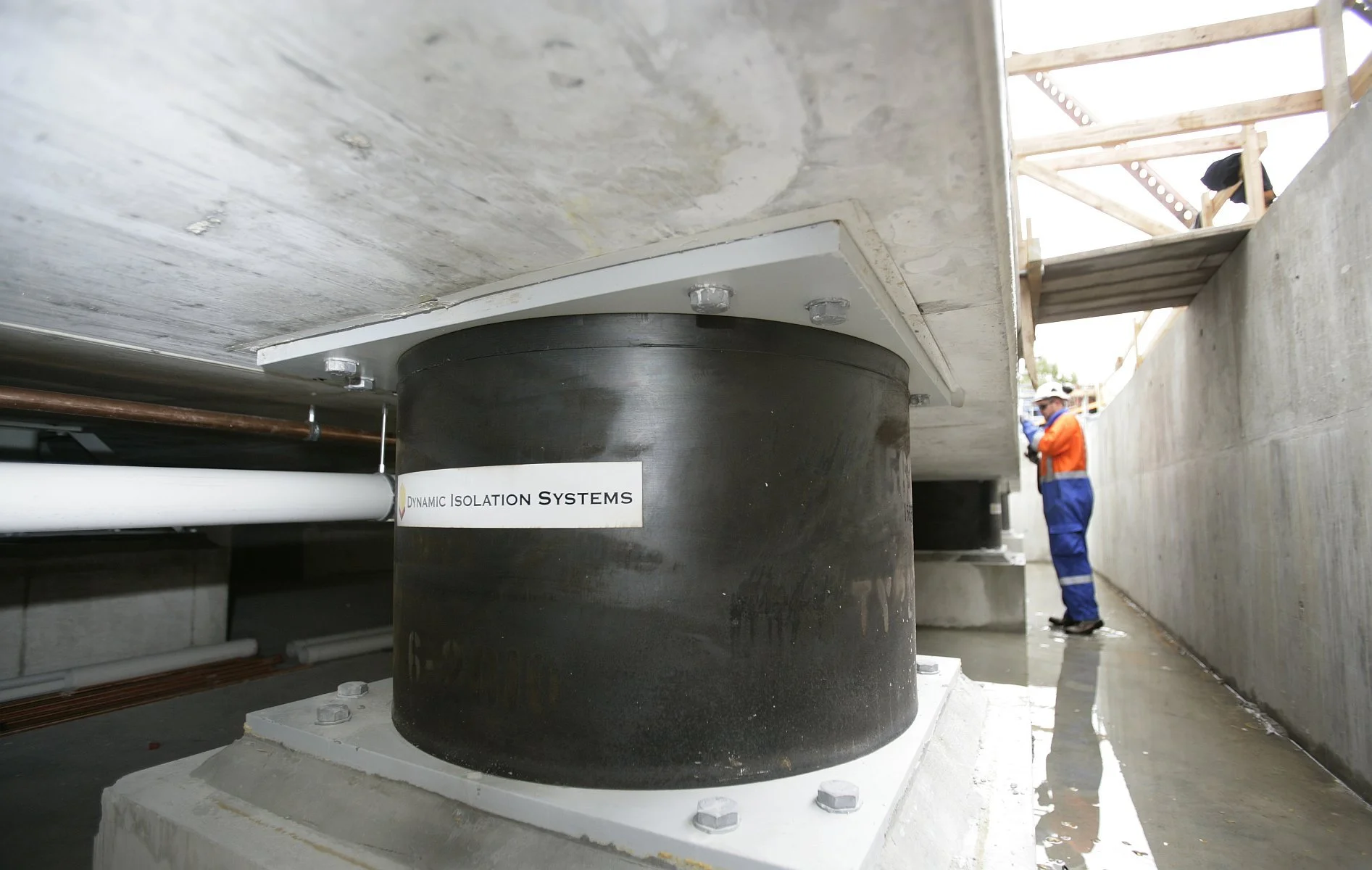
Deep Foundation Design

For the integrity of a structure, there are a number of reasons why you would want to employ a deep foundation. However, the main causes would be weakened or damaged soils, undocumented fills, and liquefaction.

A deep foundation is a type of foundation used in construction to provide support for structures by transferring the load to deeper, more stable soil or rock layers.

This is in contrast to shallow foundations, which typically transfer loads to the soil layers near the surface. Deep foundations are employed when the soil near the surface has insufficient bearing capacity, the structure's loads are very large, or when the structure is subjected to lateral forces such as wind or seismic loads.

When To Use a Deep Foundation

For the integrity of a structure, there are a number of reasons why you would want to employ a deep foundation. However, the main causes would be weakened or damaged soils, undocumented fills, and liquefaction.

Weak Soils

The term “weak soils” refers to soils that could potentially fail if a shallow foundation were to be employed.

Compressible Soils

Compressible soils are those that can become denser through the process of volume reduction. Fundamentally, the soil will compress and pull down over time when a structure is built on compressible soil without deep foundation

Undocumented Soils

When the soil’s stability is unknown, it is referred to as undocumented soil.

Liquefaction

Liquefaction occurs when waterlogged, loosely packed sediments at or near the ground’s surface start to lose strength as a result of violent ground shaking. During earthquakes, liquefaction beneath buildings and other structures can result in significant damage.

Types of Deep Foundations

The following are the several kinds of deep foundations now in use:

  • Basement foundations

  • Buoyancy rafts (hollow box foundations)

  • Caisson foundations

  • Drilled shaft foundations

  • Pile foundations

Basement Foundations

These are hollow underground buildings intended to give workspace or storage. Instead of taking into account the most effective way to withstand external earth and hydrostatic pressures, the structural design is dictated by their functional needs. They are built on-site in open excavations.

Buoyancy Rafts( Hollow Box Foundations)

Buoyancy rafts, also known as floating foundations or float-out installations, are a type of foundation system used in the construction of structures on poor or saturated soil conditions where traditional foundations may not be suitable. These foundations work by using the principle of buoyancy, where the weight of the structure is counteracted by the buoyant force exerted by the displaced soil or water. This reduces the overall bearing pressure on the soil, helping to prevent settlement and instability.

Buoyancy rafts are typically constructed using lightweight materials such as reinforced concrete, and their design may incorporate hollow or cellular sections to further reduce the weight of the foundation. The structure's weight is evenly distributed across the buoyancy raft, which in turn displaces an equivalent volume of soil or water to generate buoyant uplift.

These types of foundations are commonly used in areas with high water tables, marshy lands, or very soft soils, where the bearing capacity of the soil is low or where settlement is a significant concern. They can also be used in areas with environmental constraints or contamination, where minimizing ground disturbance is essential.

It is important to note that the design and construction of buoyancy rafts require careful engineering and analysis to ensure the proper balance between the structure's weight and the buoyant force. This helps maintain stability and prevent excessive uplift or settlement.

Caisson Foundations

A caisson foundation, also referred to as a pier foundation, is a watertight retaining structure used as a bridge pier, in the construction of a concrete dam, or for ship repairs. It consists of a prefabricated hollow box or cylinder that is used as a foundation and is lowered into the ground to a particular depth before being filled with concrete.

When constructing bridge piers and other structures that must be anchored beneath rivers and other bodies of water, the caisson foundation is most usually used. This is made possible by the ability to float caissons to the project site and then bury them there.

If a geotechnical engineer determines that the soil is suitable to carry the building load, caissons are either drilled deep into the underlying soil strata or to bedrock (referred to as “rock caissons”). Caissons are typically “belled” at the bottom when they rest on soil to disperse the weight over more ground. For these “belled caissons,” specialized drilling bits are used to remove the soil.

Types of Caisson Foundations

There are various types of caisson foundations, they include;

  • Box Caissons

  • Excavated Caissons

  • Floating Caissons

  • Open Caissons

  • Pneumatic Caissons

  • Sheeted Caissons

Box Caissons

Box caissons are heavy-timbered, watertight boxes with an opening at the top. They are often floated to the proper location, where they are then buried into the ground with a masonry pier inside.

Excavated Caissons 

Excavated caissons are exactly what their name implies—caissons that are erected inside an area that has been dug out. They are typically cylindrical in shape, with a concrete backfill.

Floating Caissons 

Floating caissons are prefabricated boxes with cylindrical cavities, commonly referred to as floating docks.

Pneumatic Caissons

Little cofferdams called open caissons are positioned, pumped dry, and then filled with concrete. They are typically utilized while building piers.

Sheeted Caissons 

Large waterproof cylinders or boxes called pneumatic caissons are typically utilized for underwater construction.

Cylinders

Cylinders are small single-cell caissons.

Drilled Shaft Foundations

Drilled shaft foundations, also known as drilled piers or bored piles, are a type of deep foundation used to support structures by transferring loads to deeper, stable soil layers or bedrock. Constructed by drilling a large diameter hole, inserting a steel reinforcement cage, and filling it with concrete, they are suitable for a wide range of soil conditions and provide high load-bearing capacity and resistance to lateral loads. Commonly used for bridges, tall buildings, and other structures, drilled shaft foundations are a reliable alternative when shallow foundations are insufficient.

Pile Foundations

The most typical deep foundation, which is frequently utilized for big projects. Pile foundation is appropriate when the soil is clayey or has a low bearing capability. Concrete, steel, and timber are all utilized to make piles, but reinforced concrete is most frequently used for pile foundations. Through a vertical pile, the load will be transferred from the superstructure to the deep-seated soil.

Types of Pile Foundation

There are several types of pile foundations in use. They are;

  • End bearing pile

  • Friction pile

  • Anchor pile

End Bearing Pile

The end bearing piles are driven into the hard, soft soil at a depth of no more than 40 meters. Over the hard rock, at a great depth, the pile’s end is set. Through the vertical elements of the foundation, the structure’s load will be transmitted to the ground soil.

Friction Pile

The end-bearing pile is driven using the same methods as the friction pile. When the pile depth is greater than 40 meters, the friction pile is used. The weight Is transferred by the skin friction that occurs when the friction piles happen by the surrounding dirt.

Anchor Pile

A particular kind of pile foundation called an anchor pile is utilized to withstand uplift forces that may otherwise cause the pile to be pulled out of the earth.

Advantages of Deep Foundations

  • They can withstand heavy loading conditions

  • High-rise buildings can be built in areas with poor soil holding ability.

  • Utilized for large-scale building structures.

  • It is impact-resistant against seismic loads.

Disadvantages of Deep Foundations

  • Building a deep foundation is expensive.

  • A highly skilled workforce is needed.

  • While executing, many additional safety precautions are needed.

Deep Foundations Design Steps

Deep foundations are structural components that divert stresses away from weak or unstable surface soils and onto deeper, more stable soil layers or rock formations. When high bearing capacity and resistance to lateral stresses are required for buildings, bridges, dams, and other structures, they are frequently used. Yet, there are a number of difficulties involved in planning and constructing deep foundations on slopes that are prone to landslides, including slope stability, soil-structure interaction, seismic stress, and construction viability. Listed below are some of the steps required to carry out an effective deep foundation design.

  • Slope Stability Risk Assessment

Assessing the danger of slope failure and its potential effects on the effectiveness of the foundation is the first stage in any foundation design. The evaluation of the geotechnical qualities of the soil, the geometry and orientation of the slope, the groundwater conditions, the external loads and stresses, and the probable collapse causes and modes all come under the complicated and site-specific process known as slope stability analysis. Several techniques and tools, such as limit equilibrium analysis, finite element analysis, probabilistic analysis, or physical and numerical modeling, might be employed, depending on the level of specificity and precision required.

A factor of safety (FOS), which represents the margin of safety against slope failure, is the result of the slope stability analysis. If the FOS is less than 1, the slope is unstable; if it is more than 1, the slope is stable. The project needs, the level of uncertainty, and the design codes all affect the minimum allowable FOS.

  • Selection of Suitable Deep Foundation

There are several options to take into account when choosing the best deep foundation type for the slope conditions and the structural requirements, including piles, drilled shafts, caissons, micropiles, helical piles, and ground anchors. Depending on the soil type, installation technique, load capacity, stiffness, durability, and cost, each type has pros and cons. Certain general standards should be considered while making a choice.

The selected foundation must have the following properties: it must be capable of withstanding vertical, horizontal, and moment loads from the structure and slope movements; it must be able to pierce through weak or unstable surface soils and reach a competent bearing layer or rock formation; it should have a minimal impact on the slope stability and soil-structure interaction; and it should be practical to install with the equipment and resources currently available without causing excessive disturbance or damage to the slope or environment.

  • Design And Analysis of Deep Foundation

The axial and lateral load capacities of the foundation, as well as its settlement and deflection, must all be taken into account when building and analyzing deep foundations on slopes that are prone to landslides. The foundation’s ability to support a seismic load should also be considered, as well as interactions between nearby foundations that could have an impact on the system’s load distribution and collective efficiency. These elements must all adhere to design guidelines and standards.

  • Installation And Monitoring of Deep Foundation

The deep foundations on the slope must be installed and maintained as the final phase, in accordance with the contract requirements and design criteria. Quality control, instrumentation, and observation should all be taken into account during installation and monitoring, as well as the manner and order of installation. The foundation materials may need to be tested and inspected, and measurements and records of displacement, load, strain, stress, and vibration may need to be made both during and after installation in order to confirm the design assumptions and find any anomalies or issues.

Got a project you need professionals for? Let's help you get started on it! You can speak with our professionals at JPC Design Consortium to get you started on your project today. We also give consultation services just in case you need some specific advice for your project. Contact us right away. 

Read More
STRUCTURAL ENGINEERING Daniel M. STRUCTURAL ENGINEERING Daniel M.

Structural Analysis and Design of Bridges

Bridges are a critical piece of infrastructure that connects people and communities. They are built to span over rivers, valleys, and other obstacles that would otherwise impede travel and transportation. But building a bridge is no easy feat - it requires a complex process of structural analysis, design, and construction to ensure that the bridge is safe, durable, and functional. In this article, we will dive into the world of bridge engineering and explore the steps involved in creating a bridge from start to finish.

Structural Analysis

The first step in building a bridge is to conduct a structural analysis of the site. This involves evaluating the location, the environmental conditions, and the load-bearing capacity of the ground. The location of the bridge is crucial as it will determine the type of bridge that is most appropriate for the site. For example, a suspension bridge is ideal for spanning long distances over deep water, while a beam bridge is better suited for shorter distances over shallower water.

Environmental conditions also play a critical role in bridge design. The design must take into account factors such as wind, seismic activity, and temperature changes. Bridges built in areas prone to earthquakes, for example, must be designed to withstand strong lateral forces.

Finally, the load-bearing capacity of the ground must be evaluated to determine the type of foundation that will be required. The foundation is the part of the bridge that supports the weight of the entire structure, and it must be able to withstand the weight of the bridge, as well as any additional loads that may be placed on it.

Design

Once the site has been evaluated, the next step is to design the bridge. This involves selecting the type of bridge that is most appropriate for the site, and then determining the size and shape of the structure. The design must also take into account the materials that will be used, as well as any special features that may be required.

The materials used in bridge construction can vary widely depending on the site and the type of bridge being built. Some common materials include concrete, steel, and timber. Each material has its own unique properties and advantages, and the selection of materials will depend on factors such as cost, durability, and environmental impact.

Special features may also be required in the design of the bridge. For example, a bridge built in an area with high winds may require the use of aerodynamic features to reduce wind resistance. Similarly, a bridge built in an area with heavy traffic may require wider lanes or additional safety features such as barriers or guardrails.

Construction

With the design complete, the final step is to construct the bridge. This is a complex process that requires a team of skilled engineers and construction workers. The construction process typically begins with the foundation, which must be excavated and prepared to support the weight of the bridge.

Once the foundation is in place, the construction team will begin to assemble the bridge. This typically involves the use of cranes and other heavy equipment to lift and place the various components of the bridge into position. The components of the bridge may include the piers, girders, and decking.

As the bridge is assembled, the construction team must constantly monitor the structure to ensure that it is being built to the specifications of the design. This may involve performing tests on the materials or conducting simulations to evaluate the performance of the bridge under various conditions.

Once the bridge is complete, it must be inspected to ensure that it is safe and functional. This typically involves a series of tests and inspections to evaluate the strength, stability, and durability of the bridge.

Conclusion

Building a bridge is a complex and challenging process that requires a combination of technical expertise and creativity. From the initial structural analysis to the final inspection, every step in the process is critical to ensuring that the bridge is safe, durable, and functional. As our communities continue to grow and expand.

Have a bridge design project to handle? Kindly contact us on jpcdesignconsortium.com/contact-us for a consultation.

Read More
STRUCTURAL ENGINEERING Daniel M. STRUCTURAL ENGINEERING Daniel M.

Structural Performance And Behavior of Timber

The use of timber as a structural material is not new. It stretches back many centuries and predates the invention of concrete and steel as structural elements. Modern advanced timber products are now readily available, enabling structural engineers to achieve the performance and efficiency required in the 21st century construction industry. With the passage of time, advancements in the various types of timber elements available and their use in different structural forms have taken place.

Mass Timber

Timber is a material that can be used for many different structural forms, including beams, columns, trusses, and girders. It can also be used for piles, deck members, railway sleepers, and concrete formwork.

Timber is an ideal building material due to a number of its inherent qualities. They include its remarkable durability and performance record, high strength to weight ratio, and good sound and heat insulation qualities. The natural development properties of timber, such as grain patterns, colors, and availability in a wide range of species, sizes, and shapes, make it a material that is remarkably adaptable and visually beautiful. Wood may be easily formed and joined together with the help of bolts, screws, dowels, and adhesives.

When constructed, treated, and detailed properly, wood constructions can be very long-lasting. Historic structures all across the world have examples of this. Wooden constructions are easily reconfigured or modified, and they may be fixed if they are damaged. Comprehensive information on the material qualities of timber, its reconstituted products, and engineered goods, as well as their implications on structural design and service performance, has been developed as a consequence of extensive research over the past few decades. Our knowledge of safe construction practices, connecting details, and design restrictions is based on much experience and research on using timber in buildings.

Types of Timber And It’s Applications

When referring to the wood-based structural products, the word “timber” is frequently employed. Timber is divided into two categories: “softwood” and “hardwood.” Coniferous trees provide softwood, whereas broad-leaved trees provide hardwood. The words “softwood” and “hardwood” are botanical in nature and may not always indicate how dense or hard the wood is. For instance, Douglas Fir is a softwood with strong durability and high strength properties, whereas Balsa, which is known to be soft and utilized for making lightweight models, is a hardwood.

Softwood is commonly used for wooden buildings because it is easily available, well utilized, reasonably inexpensive, and because of its high growth rate, which ensures a steady supply from regenerated forest areas. When strength and specific aesthetics, like as color or grain pattern, are required, hardwoods are typically employed in exposed frameworks and cladding.

Structural Properties And Performance of Mass Timber

The structural performance and behavior of mass timber is a function of several properties including its strength, moisture content, creep, durability and fire resistance.

Strength

The intrinsic qualities of the wood and the way the tree grows give mass timber its strength. The roots of trees are sawn to create typical wooden joists. The roots are surrounded by cells that make up the trunk; these cells are long relative to their breadth. These cells, which provide axial and flexural support, are parallel to the circumference of the timber joists and beams that are sawed from the tree stem. Timber that is parallel to the grain has an even higher stress and strain capacity than timber that is perpendicular to the grain because of the inherent characteristics of these cell arrangements.

The strength of sawn wood depends on its species, width, size, and member shape, as well as on the moisture content, length of loading, and strength-eroding traits such as grain slope, knots, fissures, and wane. Strength grading techniques were established to differentiate timber using either machine strength grading techniques or visual force grading techniques.

According to ANSI/AWC NDS 2016, a set of resistance groups is formed from timbers with similar strength characteristics. This streamlines the design and development process by enabling projects to be constructed within defined strength class boundaries without the need to categorize and procure a specific combination of species and grades. Coniferous prefixed softwoods and deciduous prefixed hardwoods are the terms used to describe the strength classes.

Moisture Content

The water from the tree sits inside the cell walls and voids immediately after it has been felled. The moisture content (m/c, the weight of water to oven-dry timber) decreases as the wood dries, and water is then removed from inside the cell voids without dimensional adjustment. This process continues until the “fibre saturation stage” (about 25% m/c), at which point water begins to be removed from the cell walls. The next step is the beginning of shrinkage, often known as dimension change.

The strength and rigidity of a piece of wood can be affected by its moisture level, which normally increases the strength of the wood as the moisture content decreases. The level of construction quality has to do with the wood’s natural strength at a moisture content that complies with the requirements of Service Classes 1 and 2. Timber is considered wet at a moisture content of 20% or more (Service Class 3), and stresses decrease as moisture content rises to 30%. According to standard calculations, the dimensions of wood perpendicular to the direction of the grain change by 1% for every 4% change in moisture content.

Creep

“Creep” is a significant characteristic of timber that has an impact on its effectiveness and serviceability. When originally loaded, wood deforms elastically; nevertheless, as time passes, more deformation takes place.

As the moisture content of the timber increases and the load is applied for longer periods of time, the quantity of creep deformation would increase. For instance, the creep can increase the initial deflection of a Service Class 2 sawn timber joist by up to 80%.

Durability

Depending on the plant, several levels of inherent durability exist for timber materials. When moisture builds up to this level due to structural flaws in a building or poor maintenance, timber rot can often occur if the moisture content is over 22% over an extended period of time.

Chemical preservation treatments may be used when a non-sustainable specie needs durability against the likelihood of degeneration or insect attack. Preservatives are also employed as a secondary line of “insurance” against production or design flaws that can cause moisture contents above 22%.

For projects requiring natural durability, such as exposed timber columns, bridges, and water-holding structures, a structural engineer may instead choose to work only with a particular species of wood.

Fire Resistance

As a flammable substance, wood has the potential to ignite and quickly spread flame across its surface. However, carbon buildup on the top (in the form of charred wood) restricts the oxygen supply to the underside wood and serves as an insulator, keeping the wood below the charred level relatively cool and preserving its structural integrity.

By taking into account the characteristics of the deteriorated section beneath the charred timber, solid timber of broad cross section can therefore be manufactured without additional fire protection. As an alternative, plasterboard or other fire-resistant linings can be used to cover the wood. By applying a surface coating or chemically infusing exposed timber surfaces, the ignitability and surface spread of flame can be decreased.

Factors That Affect The Structural Behavior of Timber

Timber shouldn’t degrade under ideal circumstances, however when utilized outdoors or in exposed environments, it can degrade for a number of different natural reasons. Some of them are:

Timber Defects

The structure of naturally grown wood is distorted by the process of converting logs into structural timber. This wood is known as in-grade wood, because it has less desirable qualities than clear wood. This is because there are traits or flaws that weaken the wood, including knots, grain slopes, gum veins, reaction wood, etc. As a result, it is necessary to test in-grade specimens in accordance with defined techniques in order to ascertain the dependable mechanical properties of the in-grade timber.

Moisture Content

The influence of moisture content on the qualities of timber varies with relation to the property being evaluated. The failure mechanism in bending is moisture dependent, and the bending strength decreases as the moisture content rises.

Bending failures typically happen in the tensile zone with low moisture contents, while at high moisture contents, failures typically happen in the compression zone. Stress modification variables are included in design codes all around the world to take moisture influence into account.

Loading Duration

Strength and stiffness are both significantly influenced by the duration of the load. The strength of a timber member decreases with increasing load duration for a fixed load size. In other words, the long-term strength for constant loads like self-weight or dead loads is only about 60% of that for the timber when it is first loaded in a structure. This loss of strength may be as high as 40%. On the other hand, for members subjected to rapidly applied and extremely short term loading, such as peak wind occurrences, the period of load effect on strength is smaller and the load carrying capacity is larger.

Fire And Temperature

Wood is a flammable material that will catch fire if exposed to it. Plasterboard, for example, is typically used as a fire-resistant covering to shield light structural members from flames. The strength of wood is constant within the normal range of ambient temperatures, however at higher temperatures, strength levels are often decreased. Strength recovery is feasible if exposure to higher temperatures is brief. However, depending on the temperature and length of exposure, prolonged exposures typically cause severe damages. Using intumescent coatings or soaking wood in salts that are flame or fire retardant can protect it against fire.

Structural Benefits of Timber

Timber is a sustainable and environmentally friendly building material with exceptional ecological features. It has low embodied energy and serves as a carbon sink. Hence, compared to other building materials like steel and concrete, the energy needed to transform trees into wood and subsequently structural timber is far lower.

Although timber can come in a wide variety of species, it can also have high heat and sound insulation qualities, as well as good durability features. Timber has a very high strength-to-weight ratio. Softwood timber is also less dense than other building materials. With smaller foundation loads and easier lifting of prefabricated components during transit and assembly, it can therefore offer lightweight structural solutions.

Prefabrication is encouraged by the use of timber as a structural material. Prefabricated off-site materials are used to build many modern constructions. There is therefore a general requirement for less on-site activity and a shorter service period for on-site work. Prefabrication, in turn, provides a purpose for quality control and eliminates the whims of weather and site conditions.

Got a building project you need professionals for? Let's help you get started on it! You can speak with our professionals at JPC Design Consortium to get you started on your project today. We also give consultation services just in case you need some more information for your project. Contact us right away. 

Read More
STRUCTURAL ENGINEERING Daniel M. STRUCTURAL ENGINEERING Daniel M.

Seismic Retrofitting of Tall Buildings And Skyscrapers

A skyscraper is a tall, continuously livable structure with multiple stories. The phrase was first used to refer to a structure with at least 35 to 50 stories, typically used for commercial, industrial, and residential uses. A tall structure is also referred to as a skyscraper.

Skyscraper design and construction require making livable, safe places in extremely tall structures. The structures must bear their weight and withstand wind and earthquakes, as well as defend residents from fire. However, they must also be easily accessible, even on higher floors, and must offer the residents with utilities and a comfortable environment. Given the delicate balances between engineering, economics, and construction management, skyscraper design issues are among the most challenging.

Seismic Retrofitting

Retrofitting is the process of integrating new features or technologies into existing systems in order to increase the stability of the building. It involves making modifications to an existing structure in order to safeguard it against flooding and other dangers like strong winds and earthquakes.

Seismic retrofitting refers to the alteration of current structures to increase their resistance to seismic activity, ground motion, or soil failure as a result of earthquakes. Seismic retrofitting is clearly necessary, as evidenced by our growing understanding of the seismic demand on structures and by the recent occurrence of significant earthquakes close to urban areas.

Seismic retrofitting is an advancement in building technology that addresses the effects of natural catastrophes on structures and their increasing frequency and intensity.

Need for Seismic Retrofitting of Tall Buildings And Skyscrapers

  • To protect the security and safety of a facility, its occupants, the machinery, equipment, and supplies.

  • Necessary to lower the risk and losses caused by non-structural factors.

  • Primarily focused on structural upgrades to lower seismic risk.

  • Hospitals are an example of a building that has to be strengthened since its services are seen to be crucial immediately following an earthquake.

Seismic Retrofitting Strategies For Tall Buildings And Skyscrapers

Following the introduction of new seismic regulations and the accessibility of modern materials (such as fiber-reinforced polymers (FRP), fiber reinforced concrete, and high strength steel), seismic retrofitting (or rehabilitation) solutions have been developed over the past few decades.

  1. The use of base isolation technologies and/or additional damping to reduce the seismic demand.

  2. Enhancing the local carrying capacity of structural components. This approach takes a more cost-effective approach to upgrading local capacity (deformation/ductility, strength, or stiffness) of specific structural components because it recognizes the inherent capacity within the current structures.

  3. Retrofitting with selective weakening. This is a counterintuitive approach to changing the structure’s inelastic mechanism while maintaining its intrinsic capacity.

  4. Having movable connections, to allow for more movement between seismically independent structures.

  5. Adding seismic friction dampers to add dampening and a configurable amount of extra stiffness at the same time.

More comprehensive methods of building retrofitting, such as combined seismic and energy retrofitting are also being investigated, and more research is being done in these areas. By combining seismic strengthening with energy retrofitting, these integrated techniques will optimize cost reduction while enhancing the seismic and thermal performance of structures.

Seismic Retrofitting Techniques for Tall Buildings And Skyscrapers

Buildings made of concrete that are susceptible to earthquake-related damage and failure must use seismic retrofitting techniques. Every year for the past 30 years, there have been earthquakes of moderate to severe intensity. These occurrences cause failures and damage to concrete structures.

Thus, the goal is to concentrate on a few particular procedures that could advance practice for the assessment of the seismic vulnerability of important existing reinforced concrete structures and for their seismic retrofitting using various cutting-edge techniques like base isolation and mass reduction. Some of the most widely used retrofitting techniques are:

  1. Adding New Shear Walls

This method is frequently used to update tall buildings with non-ductile reinforced concrete frames. Precast or cast-in-place concrete components may be used as the additional pieces.

Shear walls are commonly used for seismic retrofitting of existing structures. These walls are designed to resist lateral forces, such as those generated by earthquakes, by transferring the loads to the foundation. They are typically made of reinforced concrete, masonry, or wood and are strategically placed throughout the building to provide stability and reduce the potential for collapse during a seismic event. Shear walls can be added to existing structures by attaching them to the building frame or by constructing them as freestanding elements within the building. The use of shear walls for seismic retrofitting is an effective and widely used approach to enhance the safety and resilience of structures in earthquake-prone regions.

2. Integrating Steel Bracing

Steel bracing is a common method used for seismic retrofitting of existing structures to improve their ability to withstand earthquakes. Bracing involves the installation of steel members in a diagonal pattern to transfer the seismic forces acting on the structure to its foundation. The bracing system provides additional support and stiffness to the structure, reducing its susceptibility to damage during a seismic event. Steel is a popular material for bracing because of its high strength, ductility, and durability, which allows it to withstand significant seismic forces. Proper design and installation of steel bracing can significantly improve the seismic performance of a building and help ensure the safety of its occupants.

Jacketing

Jacketing is a popular technique for seismic retrofitting of existing buildings. In this technique, a new layer of reinforced concrete is added to the existing structure, which increases its strength and stiffness. The new layer also provides additional protection against earthquake-induced damage. Jacketing is particularly useful for buildings that were constructed before the development of modern seismic design codes and standards. The technique can be applied to a variety of building types, including concrete, masonry, and steel buildings. The effectiveness of jacketing depends on several factors, such as the quality of the existing structure, the design of the new layer, and the quality of construction.

Base Isolation

Base isolation describes the separation of the superstructure from the ground. It is the most effective tool for controlling passive structural vibration. Base Isolation is also known as Seismic Isolation.

Base isolation ensures that the structural components of the superstructure significantly dissociates from the ground's trembling, preserving the integrity of the building and improving its seismic performance. Both freshly constructed buildings and seismic upgrades of existing structures can use this earthquake engineering method, which is a type of seismic vibration control.

The process of retrofitting a building with base isolators typically involves the following steps: First, the building is evaluated to determine the type and amount of base isolators required. Then, the building's foundation is reinforced to ensure that it can support the additional weight of the isolators. Next, the isolators are installed between the building's foundation and its superstructure, using a combination of grout, anchor bolts, and steel plates to ensure a secure connection. Finally, the building is reconnected to the utilities and the surrounding infrastructure, and any necessary modifications are made to the interior and exterior finishes. The result is a building that is better able to withstand the forces of earthquakes and other seismic events..

Advantages of Base Isolation
  • Building motion is separated from the ground. Lower seismic loads mean less structural damage, Minimal superstructure repair.

  • The structure can continue to be used while being constructed.

  • Does not require a significant alteration to the existing superstructure

Disadvantages of Base Isolation
  • It is expensive.

  • Unlike other retrofitting methods, it cannot be used on partial structures.

  • Implementation is difficult and inefficient.

Mass Reduction Technique

The mass reduction technique is a highly effective method for seismic retrofitting. By reducing the mass of a structure, the force generated by an earthquake can be significantly decreased. This can greatly increase the structure's resistance to seismic activity and reduce the risk of structural damage or collapse. Additionally, mass reduction can often be achieved through relatively simple means, such as removing non-essential elements or replacing heavy materials with lighter ones. Overall, the mass reduction technique is an important tool for ensuring the safety and resilience of structures in earthquake-prone areas.

Supplementary Dampers

Supplementary dampers are a commonly used strategy for seismic retrofitting, which involves modifying existing buildings to better withstand earthquake shaking. These dampers work by dissipating energy during seismic events, reducing the overall force experienced by the building. They are typically installed at the building's base or within the structure, and can be either passive or active systems. Passive dampers, such as friction or viscous dampers, rely on the physical properties of the materials to absorb energy. Active dampers, on the other hand, use sensors and control systems to adjust their damping properties in real-time, providing more precise control over the building's response to seismic events. Overall, the use of supplementary dampers can be an effective way to enhance the seismic performance of existing structures, improving their safety and resilience in the face of earthquakes.

Tuned Mass Dampers

Tuned mass dampers (TMD) are spring-based devices that use movable weights. These are frequently used in extremely tall, light constructions to lessen wind sway. In eight to ten storey buildings that are vulnerable to damaging earthquake induced resonances, similar designs may be used to impart earthquake resistance.

Slosh Tank

Slosh tanks, also known as tuned liquid dampers, are a form of seismic retrofitting that can be used to mitigate the effects of earthquakes on structures. These tanks consist of a liquid-filled container that is designed to move in response to the shaking caused by an earthquake. As the liquid in the tank sloshes back and forth, it absorbs the energy of the seismic waves, reducing the force and displacement that is transmitted to the building. Slosh tanks can be particularly effective for tall buildings that are vulnerable to the lateral forces generated by earthquakes. However, they do require careful design and installation to ensure that they function correctly, and they may not be suitable for all types of structures. Overall, slosh tanks can be a useful tool for enhancing the seismic resilience of buildings in earthquake-prone areas.

Seismic retrofitting is an important process that can help to keep buildings and other structures safe during an earthquake. If you’re looking to retrofit your building or structure, contact us for your seismic retrofitting plans www.jpcdesignconsortium.com/contact-us.

Read More
STRUCTURAL ENGINEERING Daniel M. STRUCTURAL ENGINEERING Daniel M.

Seismic Retrofitting of Historic And Heritage Buildings

Historic structures are valuable regional cultural assets that should be preserved. They can occasionally serve as a potential source of funding and a catalyst for the neighborhood’s economic revival. Of course, not every old building qualifies as historic or monumental because the criteria used to determine whether a structure is historic might vary among cultures and nations.

A building is considered historic in the United States if it is at least 50 years old, listed on or possibly qualified for the National Register of Historic Places, as well as other state or local registers, as an individual structure, or as a component structure in a neighborhood. Unless they can be deemed historic, older buildings are typically demolished and replaced by newer ones for economical and performance reasons.

Retrofitting Process of Historic And Heritage Buildings

The phrase “retrofit process” refers to a broad range of interventions, including preservation, rehabilitation, restoration, and reconstruction. The process of putting measures in place to preserve a historic property’s original shape, integrity, and materials is known as preservation.

The term “rehabilitation” describes the act of giving a property new use through repairs, additions, and renovations while retaining the qualities that communicate its historical importance. The practice of accurately restoring a structure to how it appeared at a specific time is known as restoration.

Replicating a property at a particular moment is referred to as reconstruction. In the retrofit process, choosing the proper treatment technique is a difficult decision that must be made specifically for each project.

Depending on the project’s goals, the preservation and renovation of historic buildings may involve a wide range of different technical factors, including structural performance under earthquake and wind loads, geotechnical hazards and solutions, weathering and water infiltration, fire life safety, and more.

The structural renovation or retrofit of these buildings presents many technical challenges to A/E design professionals because the design methodology, building materials, and construction techniques used in their initial construction were frequently significantly different from those used in contemporary buildings.

Materials Development in Building Construction

Building materials have changed steadily throughout the course of history, and over the past century, the rate of change has increased. Some of the primary reasons for the differences between traditional and modern building materials are developments in material engineering and metallurgy, the development of plastics and fiber-reinforced composites, and changes in the manufacture and handling of existing building materials. Improvements to traditional building materials that are employed in both old and modern structures include:

Buildings Made of Masonry, Stone, And Adobe

Up until the latter part of the eighteenth century, bearing wall buildings predominated; however, steel frame skeletons have since taken over as the standard structural form for major buildings. Masonry buildings are restricted to specific building types and distinct places in modern development.

While adobe or bricks have slightly grown into stronger, more resilient building materials with standardized shapes and sizes, natural stone has not changed. By using stronger mortar and reinforcements to give better resilience and continuity, design and construction methods for masonry buildings are improved. The use of concrete-filled blocks is another significant advancement in masonry structure construction.

Timber and wood

Although wood hasn’t seen any significant change as a natural building material, modern technology offers strength grading techniques, wooden panel products, preservation treatment procedures, and wood protection.

Concrete

Over the course of the 20th century, concrete underwent substantial change. Concretes that were stronger and more durable were produced using improved ingredients, quality control, preparation, and casting techniques. Lightweight, highly workable, shrinkage-compensating, low-porosity, and fiber-reinforced concrete kinds are now possible thanks to advancements in concrete technology, the use of additives and plasticizers, and improved cements.

Hot-rolled reinforcing steel

Regarding the physical characteristics and shape, reinforcing steel has undergone significant development. The new ribbed reinforcement bars with low carbon content offer more ductility and a stronger link between the steel reinforcement and concrete than the original square cross-section, high carbon content, and smooth surface reinforcement bars.

Structural Steel

Within the last century, structural steel’s overall strength has increased. A number of steel shapes are now deemed obsolete and are no longer produced due to changes in section size and steel form attributes. In the process of designing a retrofit, differences in strength, ductility, and weldability must be taken into account.

Design Codes

Building codes have been changed frequently in recent years based on various lessons learnt from failures (especially earthquake related failures). The method we perform structural analysis and modeling has significantly altered thanks to advances in computer technology and software design.

In general, more recent regulations tend to mandate better continuity for seismic loads, increase structural system redundancy, and take advantage of inelastic structural capacity to absorb and dissipate earthquake stresses.

Challenges Encountered in Retrofitting Historic and Heritage Buildings

Common concerns in most retrofit projects include minimizing noise, disruption, and damage to neighboring structures as well as providing temporary shoring and support. Depending on the extent of damage, cost implications, historical value of the building, assessed risk and some other factors, the preferable retrofitting options are evaluated and selected to maintain the originality of old structures and reduce removal of architectural material from the building:

No Penetration of Building Envelope

The historic fabrication is left undisturbed because the technique doesn’t include any damaging procedure. Since structural elements are frequently either incorporated in or hidden by the finishing, this strategy is only really appropriate in a very small number of situations.

Penetration Without Breakage

The accessible structural component being retrofitted just needs a few holes to be drilled, such as micro piles, and epoxy injected.

Breakage With Repair

Many times, it is necessary to execute some damaging processes in order to gain access to the structural component or to carry out a retrofit process, such as upgrading welded connections or installing base-isolators.

Replace

Components are replaced when structural components cannot be modified to satisfy retrofitting aims or when the damage or deterioration cannot be rectified. Maintaining continuity, isolating the component, and providing support to the rest of the facility are all important considerations during the replacement process.

Rebuild

When a workable retrofitting option cannot be identified, the historic structure is either completely or substantially rebuilt. The cost of this alternative is higher, and the cultural and historical values may be impacted by the loss of authenticity. Usually, when a historic building needs to be renovated, new structural members are needed.

In order to preserve the historic fabric of the building, the new structural members must be concealed or exposed as if they were relatively recent additions to the building. Since these kind of modifications can be undone in the future without affecting the building’s historic fabric, it is frequently preferred to expose new structural elements.

Modern Techniques For Retrofitting Historic And Heritage Buildings

Numerous retrofitting alternatives exist now thanks to modern equipment and materials, which can be used to reduce seismic risk or enhance structural system performance. The following is a list of some of the most popular retrofitting techniques:

Post Tensioning

For buildings made of reinforced concrete or masonry, post tensioning is seen to be one of the most effective retrofit choices since it adds strength and ductility to the entire structure with little to no disruption. Masonry has a modest tensile strength and a comparatively high compressive strength.

As a result, hauling gravity-based loads is where it excels. However, significant levels of tensile stress are also produced by in-plane shear and out-of-plane lateral stresses. Typically, these induced tensile stresses are greater than the compressive stresses, necessitating the addition of reinforcement (often in the form of steel elements) to provide the structure the required strength and ductility.

Post-tensioning the reinforcing steel can dramatically increase the degree of compressive stresses while preventing more brittle tensile failures. Basically, a high-strength steel rod is inserted through a core hole that is made in the masonry wall. The foundation serves as the rod’s anchor point at the bottom. The rod is then subjected to intense tensile forces using a jack at the top of the wall.

Base Isolation

Base isolation will significantly reduce architectural and structural damage in the occurrence of a big earthquake by altering the structure’s natural period, which is utilized to dissociate the building’s response from seismic activity. The two primary types of isolation devices that have been used are sliders and elastomeric bearings.

Composite Wraps

Masonry components and reinforced concrete can be made more ductile and stronger without requiring any penetration by using composite wraps or carbon fiber jackets. Composite wraps, which add extra confinement, are most successful when applied to reinforced concrete columns (both circular and rectangular shapes).

Micro Piles

To increase the ultimate capacity of the foundation and decrease foundation deflection, micro-piles are used in seismic retrofitting and foundation rehabilitation projects.

Epoxy

One of the most adaptable materials for structural repair and modernization is epoxy, which can be employed as a sealer, glue, or mortar. Epoxy is frequently used to bind reinforcement to concrete in order to repair bond degradation or to provide anchorage for fresh concrete.

Cost Comparison of Refitting Against New Construction

The price of upgrading a historic building depends on a variety of criteria. Information gathering, specialized technical techniques, and unorthodox building materials are needed. The retrofit design may focus on one of four performance levels (prevention of collapse, safety of lives, immediate occupancy, and functionality), depending on the project's goals.

However, the actual results of the retrofitting may fall short of higher performance goals. Retrofitting costs can match or even exceed new construction premiums. Economic considerations are not the only ones taken into account when deciding whether to execute retrofits or Involved are sociopolitical, legal, and reconstruction factors. Architects and engineers' main contribution to the decision-making process is the provision of economic and technical data, although the final choice heavily depends on rules, politics, and historical values.

Seismic retrofitting is an important process that can help to keep buildings and other structures safe during an earthquake. If you’re looking to retrofit your building or structure, contact us for your seismic retrofitting plans www.jpcdesignconsortium.com/contact-us.

Read More

Concrete and 3d Printing Technology

A cutting-edge and difficult area of research, 3D concrete printing in building applications combines the expertise of conventional construction with digital manufacturing. The industry may decide to focus on this area in the near future due to the elimination of formwork and a number of other significant advantages. Academic study and commercial applications in this field are receiving more attention.

Concrete

Cement, water, fine and coarse aggregates are combined in the proper ratios to create concrete. It is one of the crucial materials in civil engineering and is used extensively in building, flood control, bridges, roads, trains, and urban infrastructure. The issues of high pollution as well as high energy consumption in the preparation and application processes have risen in prominence with the rise in demand for concrete, limiting the green, healthy, and environmental sustainability of concrete.

Concrete 3d Printing

Buildings, homes, or construction components can now be fabricated in entirely new shapes that were previously impractical using conventional concrete formwork thanks to a technique called three-dimensional concrete printing (3DCP).

Simply defined, 3D printed concrete is concrete that has been specially mixed to easily flow through the printing machine's nozzle. The foundation of 3D printed concrete constructions is layering, with each layer being put on top of a prior layer of pumped concrete. Until the preferred structure appears, this method is repeated.

With 3DCP, there is no longer a requirement to cast concrete into molds or support structures. It is a considerably speedier and less expensive alternative to traditional construction methods because the curing time of such concrete can be as little as three days and full constructions can be built in only a few hours.

Water, cement, plus aggregates like sand and granite chippings make up the constituents of the concrete mix, which are the same as those used in other concrete combinations. The texture and quality of the dish itself determines how well it turns out. A manageable consistency reduces the possibility of pressure development that could obstruct the nozzle or harm the printing apparatus. As a result, the consistency is retained close to that of the aerated dough for construction purposes.

Since there is no need for a rigid form while building with 3D concrete printing, there is little to no material waste compared to traditional methods. In addition to eliminating the need for strenuous work, the procedure allows for the rapid creation of intricate geometrical structures.

3d Printing Materials

Cementitious Materials

There are many different types of cementing ingredients for 3D-printed concrete, but the most common ones include; geopolymer portland cement, resin, sulphoaluminate cement, and others. The setting time, bonding ability, strength and stability of concrete structures made via 3D printing can all be adjusted in some way by using cementitious materials.

Aggregates

Directly or indirectly, aggregate has an impact on the internal structure of concrete, affecting its viscosity, rheology, stress characteristics before and after hardening, and durability. The aggregate particle diameter significantly affects the properties of the 3D printed concrete. Extrusion nozzle blockage occurs when aggregate particle size is larger. On the other hand, if the aggregate particle size is too tiny, the aggregate’s specific surface area will expand and there will be more paste needed to cover its surface, which will end up making the concrete more brittle and susceptible to cracking.

Mineral Admixtures

The active components of mineral admixtures can significantly increase the density, durability, and service life of the structure as well as the strength of 3D printed concrete components. Fly ash can be efficiently added to printed concrete to increase its durability, mechanical qualities, and operating performance. The primary admixture used to create high-performance 3D printed concrete is fly ash.

Fiber Material

Both the maximum load's elastic modulus and the printed concrete's crack resistance can be greatly increased by fibrous elements. Additionally, it can considerably increase the hardness, ductility, and longevity of printed concrete as well as postpone the deterioration of the product's surface. With the inclusion of polypropylene fiber, printed concrete samples can be kept from peeling off, the extrusion of the concrete in the printer output port can be somewhat optimized, and a uniform and continuous printed sample structure can be obtained.

Factors That Determine The Printability of 3d Concrete

Fluidity

Fluidity is the capacity of concrete materials to smoothly extrude from the discharge port of the print head, readily pumped and transported. It is a vital aspect to take into account while determining printability. Small fluidity is likely to cause equipment blockage and premature mechanical wear. If the fluidity is high, the printed portions are easily collapsed. Fluidity must be adequately adjusted in order to suit printing requirements. Fluidity is mostly affected by water content.

Extrudability

Extrudability is a term used to describe both the difficulty of extruding concrete in three dimensions as well as the consistency and surface quality of the resulting material. The feed pipe and nozzle of the print head’s nozzle can be used to constantly convey the slurry thanks to the research of extrudability. In addition to guaranteeing the integrity of the printing building, it is a guarantee for continued printing construction.

Buildability

Buildability is a term used to describe how much the 3D printed cement-based material deforms and how stable it remains overall after being extruded under its own weight and after the resulting extrusion and gravity of the printed layer.

Importance of concrete 3d printing

When compared to traditional techniques, 3D concrete printing technology has a lot of benefits. Some of them are;

  • Eco-friendliness

By doing away with the necessity for a framework, 3D concrete reduces the amount of raw resources that would otherwise be wasted. A exact and accurate amount of cement is deposited at a time by the printer needed for 3DCP, reducing CO2 emissions and consequently our carbon footprint.

  • Ease of Concrete Customization

Since 3D concrete printing technology may be utilized to precisely construct elaborate or asymmetrical patterns, architects and builders can simply add originality and innovation to their projects. Extruded surfaces and a variety of shapes may be produced quickly and with little likelihood of human error. This is as a result of the material being deposited precisely using cutting-edge machinery.

Modern concrete mixtures that incorporate foam exhibit thermal mass properties similar to those of conventional concrete. The adoption of 3D concrete printing technology for mass production may be made practical in the future with similar breakthroughs in concrete mix formula.

  • Cost Efficient Construction

Castings and frameworks are practically unnecessary with 3DCP because it does not call for manual filling of molds by employees, as is the case with previous methods. By operating at a steady rate and lowering the amount of concrete needed, contractors may also make sure they stay within their budget by saving money on time, materials, and labor. These elements work together to make 3D concrete printing technology economical.

Because it can be built quickly, 3D concrete printing technology is a good option for creating accommodations during emergencies like natural disasters. In addition to increasing resilience of 3D printed concrete structures, the creation of hardened cement paste that is resistant to cracking makes them perfect for large-scale rehabilitation projects.

  • Increased Safety 

Automated construction using 3D concrete printing technology eliminates the need for physical labor on construction sites. Therefore, risky tasks that have an impact on the on-site safety of construction workers, including working at heights, can be completely removed from the construction project.

Limitations of Concrete 3d Printing

  • Not Appropriate in all Environments 

The hydration process of concrete causes unstable reactions to higher temperatures. When pouring concrete in even layers during inclement weather or periods of excessive heat, this provides a difficulty. Tests of 3DCP samples, for instance, have produced less favorable results when conducted in deserts.

  • Equipment Size Limitations 

Printers for 3D concrete printing must be large—ideally, bigger than the project being created. This can necessitate the requirement for specially manufactured printing equipment made for the project.

The development of 3D concrete printing technology is still in its testing stages, during which different equipment, formulations, and approaches prototypes are put to the test. Making automated machinery is an expensive endeavor because equipment is the most expensive part of any 3D concrete printing project.

  • Legal Constraints

The current limitations of the legal framework governing 3DCP projects have led to uncertainty surrounding the duties and rights of owners, builders, and manufacturers.

The rules need to be improved in areas including safety, social repercussions, the impact on the job market, and environmental effects. From a legal perspective, it is currently unexplored area.

Applications of 3D Concrete Printing Technology

  • Military

Fox News reports that American Marines have used specialized 3D concrete printers to accomplish two projects. The first project, which was completed in 2018, involved building a footbridge out of reinforced concrete. The first project took 14 hours to finish, whereas the second project took less than 40 hours to create a 500 square foot barracks area.

The United States Is effectively using 3D printed concrete for military projects, and this material has a lot of potential for supporting the military in both active and inactive battle zones.

  • Housing and Infrastructure

A similar-sized 3D printed house might cost as little as $10,000, compared to the typical cost of $40,000 to build a small American home between 200 and 400 square feet. The residential housing sector could greatly benefit from 3D printing, as costs are anticipated to fall as technology advances.

Single-family homes can be constructed in under 24 hours, as opposed to up to 6 months using traditional building techniques. The first livable 3D-printed concrete homes will be constructed in the Netherlands using 3DCP technology. The buildings will have a mound-like layout similar to that of Fred Flintstone’s home. The first structure in this undertaking, Project Milestone, will be finished in 2019 and will offer thousands of inhabitants affordable homes.

Additionally, 3D concrete has the potential to be used to build safe, affordable housing for people living in poverty. China has successfully constructed an 11,840 square foot, five-story apartment building in Suzhou, so the Netherlands is not alone in its endeavor. Additionally, it took 450 hours to construct the longest 3D-printed concrete bridge in the world in Shanghai.

Similarly, Dubai hopes to become the center of 3D construction by 2030 by using 3DCP technology to build 255 of its major construction projects.

Concrete 3D Printing Techniques

Currently, 3D concrete printing uses three different construction techniques: layered material extrusion, robotic slip forming, and binder jetting.

  • Binder Jetting

Binder jetting involves layer-by-layer selective application of a liquid binder by a print head to a substrate made of powder. The layer height, which normally ranges between 0.2 and 2 mm, affects the finished part’s speed and amount of detail. After the multilayer manufacturing is finished, binder-jetting requires post-processing processes. The unconsolidated powder must first be manually removed using vacuum tubes and brushes. In microwaves or ovens with controlled humidity and temperature, additional curing stages can also be required. Finally, coatings may be used to increase the surface quality of the part or to consolidate minor surface characteristics. Polyester or epoxy resin are common materials for coatings.

  • Layered Material Extrusion

A cementitious paste is carefully extruded in 3D printing using a numerically controlled nozzle. Typically, layers range in thickness from 5 mm to a few centimeters. The automatic troweling tool, which flattens the 3D-printed layers and fills in the grooves at the interlayer interfaces to produce a smooth concrete surface, may be used in conjunction with the extrusion nozzle.

  • Robotic Slip Forming 

Due to its additive nature, where material is progressively extruded via an actuator mould that can change its section, the technique only loosely matches the concept of 3D printing. Slip forming is more closely related to formative processes like casting and extrusion since it is a continuous process rather than a discrete or layer-based one like the other 3D printing methods.

Got an engineering project you need professionals for? Let's help you get started on it! You can speak with our professionals at JPC Design Consortium to get you started on your project today. Contact us right away. 

Read More
STRUCTURAL ENGINEERING Daniel M. STRUCTURAL ENGINEERING Daniel M.

Tall Building Structural Design and Analysis

Concept of Tall Buildings

There is no universally accepted definition of what constitutes a "tall building," but several different criteria are commonly used to determine whether a building is tall or not.

Firstly, it is critical to consider the urban context of the building. If a 10-story building is surrounded by 20-story high-rise buildings in a central business district (CBD), it may not be considered particularly tall. A 10-story building in a predominantly low-rise suburban area, on the other hand, would be considered a tall building.

Secondly, proportion may also play a role. Even structures with a modest number of storeys might be referred to as "tall" if they are thin. A "groundscraper," for example, that is somewhat tall yet has a vast footprint, may not be seen as tall.

Tall buildings that reach significant heights are classified into two types: A "supertall" building is 984ft or higher, while a "megatall" building is 1965ft or higher. There are currently 173 completed supertalls and only three completed megatalls worldwide.

Why are Tall Buildings Important?

Since the beginning of civilization, people have been fascinated with tall towers and buildings, which were first built for defensive and later ecclesiastical purposes. However, since the 1880s, the bulk of contemporary tall buildings have been built for commercial and residential uses. Tall commercial buildings are essentially a reaction to the great strain placed on limited land space by corporate operations' need to be as close to one another and the city center as possible.

Tall commercial buildings are commonly constructed in city centers as status symbols for corporate entities because they provide recognizable landmarks. Additionally, the growing mobility of the corporate and tourism communities has increased demand for more, typically high-rise, city center hotels.

The increasing urban population expansion and the resulting demand on limited space have had a significant impact on city residential construction. The necessity to sustain significant agricultural production, avoid a never-ending urban sprawl, and the expensive cost of land have all pushed residential constructions skyward. Local topographical limits make tall structures the only workable answer for housing needs in some cities, as Hong Kong and Rio de Janeiro.

Factors Affecting Height, Growth and Structural Form of Tall Buildings

High-rise building viability and popularity have always been influenced by the materials available, the sophistication of construction technology, and the level of development of the services required for building use. As a result, major advancements occasionally happened with the introduction of a new material, building site, or service.

For business and residential buildings, several structural systems have gradually developed to suit their divergent functional requirements. Large column-free open sections were added to modern office buildings to enable flexibility in layout in order to accommodate the various floor space requirements of different clients. Better service levels have frequently required dedicating entire floors to mechanical equipment, but the lost space can frequently be used to fit deep girders or trusses that link the exterior and interior structural systems. Light demountable partitions and glass curtain walls have mainly replaced the previous heavy interior partitions and Masonry cladding, which contributed to the reserve of rigidity and strength, leaving the basic structure to provide.

The fundamental functional need for a residential building is the provision of independent, self-contained housing units, divided by thick walls that offer sufficient fire and acoustic insulation. The partitions are repeated from story to story, therefore contemporary designs have made use of them as a structural element, giving rise to the shear wall, cross wall, or infilled-frame types of construction.

Modern architecture has also tended to contain architectural cuts and exposed construction, as well as setbacks at the top levels to accommodate daylight requirements. In order to accommodate these different features while still providing structures that were sufficiently stiff and strong, structural framing underwent radical changes. These changes gave rise to the new generation of braced frames, framed-tube and hull-core structures, wall-frame systems, and outrigger-braced structures.

Due to its even more varied and irregular exterior architectural treatment, the most recent generation of “postmodern” buildings has produced hybrid double and occasionally triple combinations of the structural monoforms used in modern structures.

Finally, erection speed is essential to getting a return on the expenditure made in such large-scale projects. Since most tall buildings are constructed in densely populated urban locations with restricted access, meticulous planning and sequencing of the construction process are essential.

Structural Engineering of Tall Buildings

The complete design team, including the architect, services engineer, and structural engineer, should ideally work together early on to settle on a structure that satisfies each individual's needs for function, safety, and serviceability, as well as servicing. Conflicting demands will almost always result in a compromise. However, except from the very highest skyscrapers, the architectural requirements of space arrangement and aesthetics will always come first. This frequently results in a structural solution that is less than perfect, which tests the structural engineer's creativity and perhaps patience.

The two main forms of vertical load-resisting components in tall buildings are columns and walls, with the latter serving as shear walls individually or as shear wall cores in assemblies. The purpose of the structure will logically lead to the provision of cores to store and transport services like elevators as well as walls to divide and enclose space. In areas that would not otherwise be supported, columns will be used to carry gravity loads and, in some types of structures, horizontal loads as well. Architecturally speaking, columns can also be used as things like facade mullions.

The weight of the building and its contents causes gravity loading, which is the structural elements’ fundamental and inevitable duty. Regardless of the building height, the weight of the floor system per unit floor area is roughly consistent because the loads on different floors tends to be similar. The weight of columns per unit area increases roughly linearly with building height because the gravity stress on columns increases as a building’s height decreases.

The second, and most likely, purpose of the vertical structural elements is to withstand the parasitic loads brought on by earthquakes and wind, the magnitudes of which will be determined by wind tunnel tests or national building codes.

As a building's height rises, the magnitude of the bending moments brought on by lateral forces on the structure increases by at least the square of the height. The relative material amounts needed for a standard steel frame's floors, columns, and wind bracing, as well as the cost associated with these as height grows, are approximately determined by the aforementioned criteria.

To generate a complete structural assembly with a lateral stiffness that is significantly greater than the sum of the lateral stiffnesses of the various vertical components, engineers design composite assemblies, such as linked walls and rigid frames. By doing this, a system that can withstand lateral forces will be developed.

Design Philosophy of Tall Buildings

The limit states design philosophy, which is now largely recognized, resulted from the probabilistic method for structural attributes and loading situations. This method's goal is to make sure that all structures and the parts that make them up are built to be durable enough over the course of their lifetimes and to withstand the worst loads and deformations that might possibly occur during construction and use.

When a structure hits any of several "limit states," or when it ceases to satisfy the specified limiting design constraints, it is regarded as having "failed" as a whole or in part. There are two primary types of limit states to consider: (A) the ultimate limit states, which correspond to the loads that could cause failure, including instability: the probability of failure must be extremely low because catastrophic events involving collapse would endanger lives and result in significant financial losses; and (B) the serviceability limit states, which involve the standards governing the building's service life and which, if violated, would result in significant financial losses. These are less important because they are more concerned with the building's suitability for everyday use rather than its safety.

A negative combination of random effects may lead to a specific limit state being achieved. For various circumstances that indicate the likelihood of specific events occurring or circumstances of the structure and loading existing, partial safety factors are used. Therefore, the underlying goal of the design calculations is to maintain the probability of any given limit state being reached below an allowable limit for the type of structure in question.

Structural Design and Analysis of Tall Buildings

Once the building's functional layout has been determined, the design process typically adopts a clearly defined iterative method. Initial member size calculations frequently use gravity loading plus an arbitrary increment to account for wind forces. The cross-sectional areas of the vertical members will be determined by the aggregated loadings from their corresponding tributary regions, with reductions to take into consideration the potential that not all floors would be subjected concurrently to their maximum live loading. Initial beam and slab sizes are frequently determined from coded mid- and end-span values or from moments and shears calculated using a simple method of gravity load analysis, such as two-cycle moment distribution.

Then, using a quick approximation analysis technique, the maximum horizontal deflection and the forces in the main structural components are checked.

Adjustments are made to the member sizes or the structural configuration if the deflection is too great or if some of the members are not strong enough. In order to disperse the load to less severely stressed components if particular members attract excessive stresses, the engineer may lessen their stiffness. Up until a good answer is found, the preliminary analysis, checking, and adjustment process is repeated.

As the client’s and architect’s visions for the building change, changes to the initial plan of the building will invariably be necessary. It will be necessary to reassess the structural design because this may require structural adjustments, or possibly a drastic rearrangement. In order to find the best solution, it could be essential to go through all the many preliminary processes again and again.

After that, a comprehensive final analysis will be performed using a more advanced analytical model to offer a final check on deflections and member strengths. Typically, this also takes into account the effects of second-order gravity loads on the lateral deflections and member forces (P-Delta effects). A dynamic study might also be required if there's a possibility that wind loading oscillations would result in excessive deflections or that comfort limits will be exceeded, or if it's important to include earthquake loading. At some point during the procedure, it will also be looked at whether differential motions brought on by creep, shrinkage, or temperature variations have any negative effects.

To create a suitable load-resisting system during the design phase, a full understanding of high-rise structural components and their modes of behavior is a requirement. Such a system should maximize the compliance of the fundamental serviceability requirements while minimizing the structural penalty for height and being effective and economical.

Got an engineering project you need professionals for? Let's help you get started on it! You can speak with our professionals at JPC Design Consortium to get you started on your project today. Contact us right away. 

Read More